بایگانی برچسب برای: بهسان اندیش

برای پی بردن به این موضوع که کدامیک از دو تکنولوژی CCD یا CMOS بهتر است و تصویر بهتری در اختیار کاربر قرار میدهد، لازم است تا ابتدا نحوه ی عملکرد هرکدام از این تکنولوژی ها را فرا بگیریم :

CCD چطور کار میکند ؟

نحوه کار CCD

همانطور که در شکل مشاهده میفرمایید، CCD دارای دو بخش اصلی مجزا از هم می باشد، بخش نارنجی رنگ که پیکسل ها را مشخص میکند و در حقیقت همان فتودیود است و بخش آبی رنگ که ترانزیستورهای مختلف، آی سی سیستم را تشکیل می دهند.
بدلیل جدا بودن فتودیود از ترانزیستورها، امکان جذب نور در این تکنولوژی در حالت حداکثر ممکن میباشد و با توجه به اینکه از یک آی سی جداگانه برای پردازش تصاویر تهیه شده توسط فتودیودها استفاده میشود هم میتوان امکانات بیشتری ( از جمله الگوریتم های حذف نویز، تشخیص چهره، تشخیص حرکت و … ) را به سیستم تصویربرداری اضافه کرد.

CMOS چطور کار میکند ؟

نحوه کار CMOS

تفاوت اصلی تکنولوژی CMOS با CCD همانطور که در شکل کاملا مشخص می باشد در این است که فتودیودها و ترانزیستورها در تکنولوژی CMOS بر روی یک برد سوار میشوند.

این روش باعث پایین آمدن مصرف انرژی نسبت به CCD و کمترشدن قیمت تمام شده ی محصول تهیه شده با تکنولوژی CMOS می شود ولی با توجه به کیفیت پایین تر و حساسیت به نور کمتر نمیتوان گفت که دوربین هایی که از تکنولوژی CMOS استفاده میکنند کارایی بهتری نسبت به دوربین های مشابه با تکنولوژی CCD دارند.

تفاوت CCD و CMOS

مقایسه CCD با CMOS :

در شکل بالا تصاویر تهیه شده توسط دو دوربین با لنزها و شرایط نوردهی یکسان توسط CCD و CMOS نمایش داده شده است. همانطور که در شکل ملاحظه می فرمایید تصاویر تهیه شده با CCD از نویز کمتری برخوردار بوهد و رنگ ها شفافیت و واقعیت بیشتری دارند.

بطور کلی اگر بخواهیم این دو تکنولوژی را با هم مقایسه کنیم میتوانیم به موارد زیر توجه کنیم :
• دوربین های CMOS حساسیت به نور کمتری دارند، لذا تصاویر دریافت شده از کیفیت پایینتری نسبت به تکنولوژی همرده در دوربین های CCD برخوردار است.
• دوربین های CMOS حساسیت بیشتری به نویز دارند.
• دوربین های CMOS در هنگام استفاده از سیستم “دید در شب” چون از راهکار “مادون قرمز” استفاده میشود که نور تک رنگ با قدرت کم در محیط وجود دارد، تصاویر مناسبی ارائه نمیدهند.
• دوربین های CMOS ارزانتر از دوربین های CCD میباشند و این به دلیل عدم استفاده از یک بورد جداگانه برای عمل پردازش تصویر می باشد.
• دوربین های CMOS مصرف انرژی کمتری نسبت به دوربین های CCD دارند و درصورتی که شما از سیستم های امنیت تصویری با باتری یا سیستم پشتیبان ( یو پی اس ) استفاده میکنید بکاربردن دوربین های CMOS به صرفه تر است.
• قابلیت های دوربین های CMOS برای تشخیص چهره، حرکت و … پایین تر از دوربین های CCD می باشد.
• دوربین های CCD با سرعت بیشتری عمل Shuttering را انجام می دهند به این معنی که عمل تصویربرداری از اجسام متحرک بهتر و واضح تر انجام می شود.

منبع

کار با Thread ها در زبان سی شارپ – آشنایی با فضای نام System.Threading و کلاس Thread

تا اینجا متوجه شدیم که چگونه می توان با کمک Delegate ها کدها را در یک Thread جداگانه و به صورت Asynchrnonous اجرا کرد. در ادامه مباحث مرتبط با برنامه نویسی Asynchronous به سراغ فضای نام System.Threading می رویم. این فضای نام شامل یکسری کلاس است که روند نوشتن برنامه Multi-Threaded را آسان می کند. کلاس های زیادی در این فضای نام وجود دارد که هر یک استفاده خاص خودش را دارد. در زیر با توضیح اولیه برخی از کلاس های این فضای نام آشنا می شویم:

  1. Interlocked: از این کلاس برای اجرای عملیات های atomic یا Atomic Operations بر روی متغیرهایی که در بین چندین Thread به اشتراک گذاشته شدند استفاده می شود.
  2. Monitor: از این کلاس برای پیاده سازی Synchronization بر روی اشیاء ای که Thread به آن دسترسی دارند استفاده می شود. در سی شارپ کلمه کلیدی lock در پشت زمینه از مکانیزم Monitor برای Synchronization استفاده می کنید که در بخش های بعدی با این تکنیک بیشتر آشنا می شویم.
  3. Mutex: از این کلاس برای اعمال Synchronization بین AppDomain ها استفاده می شود.
  4. ParameterizedThreadStart: این delegate به thread ها این اجازه را می دهد تا متدهایی پارامتر ورودی دارند را فراخوانی کند.
  5. Semaphor: از این کلاس برای محدود کردن تعداد Thread هایی که می توانند به یک Resource دسترسی داشته باشند استفاده می شود.
  6. Thread: به ازای هر Thread ایجاد شده برای برنامه باید یک کلاس از نوع Thread ایجاد کرد. در حقیقت کلاس Thread نقش اصلی را در ایجاد و استفاده از Thread ها دارد.
  7. ThreadPool: بوسیله این کلاس می توان به Thread-Pool مدیریت شده توسط خود CLR دسترسی داشت.
  8. ThreadPriority: بوسیله این enum می توان درجه اهمیت یک Thread را مشخص می کند.
  9. ThreadStart: از این delegate برای مشخص کردن متدی که در Thread باید اجرا شود استفاده می شود. این delegate بر خلاف ParameterizedThreadStart پارامتری قبول نمیکند.
  10. ThreadState: بوسیله این enum می توان وضعیت جاری یک thread را مشخص کرد.
  11. Timer: بوسیله کلاس Timer می توان مکانیزمی پیاده کرد که کدهای مورد نظر در بازه های زمانی خاص، مثلاً هر 5 ثانیه یکبار و در یک Thread مجزا اجرا شوند.
  12. TimerCallBack: از این delegate برای مشخص کردن کدی که داخل timer باید اجرا شود استفاده می شود.

کلاس System.Threading.Thread

کلاس Thread اصلی ترین کلاس موجود در فضای نام System.Threading است. از یک کلاس برای دسترسی به Thread هایی که در روند اجرای یک AppDomain ایجاد شده اند استفاده می شود. همچنین بوسیله این کلاس می تواند Thread های جدید را نیز ایجاد کرد. کلاس Thread شامل یکسری متد و خصوصیت است که در این قسمت می خواهیم با آن ها آشنا شویم. ابتدا به سراغ خصوصیت CurrentThread که یک خصوصیت static در کلاس Thread است می رویم. بوسیله این خصوصیت می توان اطلاعات Thread جاری را بدست آورد. برای مثال در صورتی که در متد Main از این خصوصیت استفاده شود می توان به اطلاعات مربوط به Thread اصلی برنامه دسترسی داشت یا اگر برای یک متد Thread جداگانه ای ایجاد شود، در صورت استفاده از این خصوصیت در بدنه متد به اطلاعات Thread ایجاد شده دسترسی خواهیم داشت. در ابتدا با یک مثال می خواهیم اطلاعات Thread اصلی برنامه را بدست آوریم:

var primaryThread = Thread.CurrentThread;
primaryThread.Name = "PrimaryThread";
Console.WriteLine("Thread Name: {0}", primaryThread.Name);
Console.WriteLine("Thread AppDomain: {0}", Thread.GetDomain().FriendlyName);
Console.WriteLine("Thread Context Id: {0}", Thread.CurrentContext.ContextID);
Console.WriteLine("Thread Statred: {0}", primaryThread.IsAlive);
Console.WriteLine("Thread Priority: {0}", primaryThread.Priority);
Console.WriteLine("Thread State: {0}", primaryThread.ThreadState);

دقت کنید در ابتدا با به Thread یک نام دادیم. در صورتی که نامی برای Thread انتخاب نشود خصوصیت Name مقدار خالی بر میگرداند. مهمترین مزیت تخصیص نام برای Thread راحت تر کردن امکان debug کردن کد است. در Visual Studio پنجره ای وجود دارد به نام Threads که می توانید در زمان اجرای برنامه از طریق منوی Debug->Windows->Threads به آن دسترسی داشته باشید. در تصویر زیر نمونه ای از این پنجره را در زمان اجرا مشاهده می کنید:

آشنایی با فضای نام System.Threading و کلاس Thread

اما بریم سراغ موضوع اصلی، یعنی ایجاد Thread و اجرای آن. در ابتدا در مورد مراحل ایجاد یک Thread صحبت کنیم، معمولاً برای ایجاد یک Thread مراحل زیر را باید انجام دهیم:

  1. در ابتدا باید متدی ایجاد کنیم که وظیفه آن انجام کاری است که قرار است در یک Thread جداگانه انجام شود.
  2. در مرحله بعد باید یکی از delegate های ParameterizedThreadStart برای متدهایی که پارامتر ورودی دارند یا ThreadStart برای متدهای بدون پارامتر را انتخاب کرده و یک شئ از آن ایجاد کنیم که به عنوان سازنده متد مورد نظر به آن پاس داده می شود.
  3. از روی کلاس Thread یک شئ جدید ایجاد کرده و به عنوان سازنده شئ ای که از روی delegate های گفته شده در مرحله 2 ساختیم را به آن ارسال کنیم.
  4. اطلاعات و تنظیمات اولیه مورد نظر برای Thread مانند Name یا Priority را برای آن ست کنیم.
  5. متد Start را در کلاس Thread را برای شروع کار Thread فراخوانی کنیم. با این کار متدی که در مرحله 2 مشخص کردیم در یک Thread جداگانه اجرا می شود.

دقت کنید در مرحله 2 می بایست بر اساس signature متدی که قصد اجرای آن در thread جداگانه را داریم، delegate مناسب انتخاب شود. همچنین ParameterizedThreadStart پارامتری که به عنوان ورودی قبول می کند از نوع Object است، یعنی اگر می خواهید چندین پارامتر به آن ارسال کنید می بایست حتماً یک کلاس یا struct ایجاد کرده و آن را به عنوان ورودی به کلاس Start ارسال کنید. با یک مثال ساده که از ThreadStart برای اجرای Thread استفاده می کند شروع می کنیم:

static void Main(string[] args)
{
    ThreadStart threadStart = new ThreadStart(PrintNumbers);
    Thread thread = new Thread(threadStart);
    thread.Name = "PrintNumbersThread";
    thread.Start();
    while (thread.IsAlive)
    {
        Console.WriteLine("Running in primary thread...");
        Thread.Sleep(2000);
    }
    Console.WriteLine("All done.");
    Console.ReadKey();
}

public static void PrintNumbers()
{
    for (int counter = 0; counter < 10; counter++)
    {
        Console.WriteLine("Running from thread: {0}", counter + 1);
        Thread.Sleep(500);
    }
}

در ابتدا متدی تعریف کردیم با نام PrintNumbers که قرار است در یک Thread مجزا اجرا شود. همانطور که مشاهده می کنید این متد نه پارامتر ورودی دارد و نه مقدار خروجی، پس از ThreadStart استفاده می کنیم. بعد از ایجاد شئ از روی ThreadStart و ایجاد Thread، نام Thread را مشخص کرده و متد Start را فراخوانی کردیم. به حلقه while ایجاد شده دقت کنید، در این حلقه بوسیله خصوصیت IsAlive گفتیم تا زمانی که Thread ایجاد شده در حال اجرا است کد داخل while اجرا شود. همچنین بوسیله متد Sleep در متد Main و متد PrintNumbers در عملیات اجرا برای Thread های مربوط به متد تاخیر ایجاد کردیم. بعد اجرای کد بالا خروجی زیر نمایش داده می شود:

Running in primary thread...
Running from thread: 1
Running from thread: 2
Running from thread: 3
Running from thread: 4
Running in primary thread...
Running from thread: 5
Running from thread: 6
Running from thread: 7
Running from thread: 8
Running in primary thread...
Running from thread: 9
Running from thread: 10
All done.

در قدم بعدی فرض کنید که قصد داریم بازه اعدادی که قرار است در خروجی چاپ شود را به عنوان پارامتر ورودی مشخص کنیم، در اینجا ابتدا یک کلاس به صورت زیر تعریف می کنیم:

public class PrintNumberParameters
{
    public int Start { get; set; }
    public int Finish { get; set; }
}

در قدم بعدی کلاس PrintNumbers را به صورت زیر تغییر می دهیم:

public static void PrintNumbers(object data)
{
    PrintNumberParameters parameters = (PrintNumberParameters) data;
    for (int counter = parameters.Start; counter < parameters.Finish; counter++)
    {
        Console.WriteLine("Running from thread: {0}", counter);
        Thread.Sleep(500);
    }
}

همانطور که مشاهده می کنید، پارامتر ورودی PrintNumbers از نوع object است و در بدنه ورودی را به کلاس PrintNumberParameters تبدیل کرده و از آن استفاده کردیم. در مرحله بعد متد Main را باید تغییر داده و به جای ThreadStart از ParameterizedThreadStart استفاده کنیم، همچنین به عنوان پارامتر ورودی برای متد Start شئ ای از PrintNumberParameters ایجاد کرده و با عنوان پارامتر به آن ارسال می کنیم:

ParameterizedThreadStart threadStart = new ParameterizedThreadStart(PrintNumbers);
Thread thread = new Thread(threadStart);
thread.Name = "PrintNumbersThread";
thread.Start(new PrintNumberParameters() {Start = 5, Finish = 13});
while (thread.IsAlive)
{
    Console.WriteLine("Running in primary thread...");
    Thread.Sleep(2000);
}
Console.WriteLine("All done.");
Console.ReadKey();

با اعمال تغییرات ذکر شده و اجرای کد، اعداد بر اساس بازه مشخص شده در خروجی چاپ می شوند. در این قسمت از مطلب مربوط به Thread ها با نحوه ایجاد و استفاده از Thread ها آشنا شدیم. در قسمت های بعدی به مباحث دیگری در مورد Thread ها خواهیم پرداخت.

منبع


قسمت اول آموزش-برنامه نویسی Asynchronous – آشنایی با Process ها، Thread ها و AppDomain ها

قسمت دوم آموزش- آشنایی با ماهیت Asynchronous در Delegate ها

قسمت سوم آموزش-آشنایی با فضای نام System.Threading و کلاس Thread

قسمت چهارم آموزش- آشنایی با Thread های Foreground و Background در دات نت

قسمت پنجم آموزش- آشنایی با مشکل Concurrency در برنامه های Multi-Threaded و راهکار های رفع این مشکل

قسمت ششم آموزش- آشنایی با کلاس Timer در زبان سی شارپ

قسمت هفتم آموزش-آشنایی با CLR ThreadPool در دات نت

قسمت هشتم آموزش- مقدمه ای بر Task Parallel Library و کلاس Parallel در دات نت

قسمت نهم آموزش- برنامه نویسی Parallel:آشنایی با کلاس Task در سی شارپ

قسمت دهم آموزش-برنامه نویسی Parallel در سی شارپ :: متوقف کردن Task ها در سی شارپ – کلاس CancellationToken

قسمت یازدهم آموزش- برنامه نویسی Parallel در سی شارپ :: کوئری های Parallel در LINQ

قسمت دوازدهم آموزش- آشنایی با کلمات کلیدی async و await در زبان سی شارپ

قسمت سیزدهم آموزش- استفاده از متد WhenAll برای اجرای چندین Task به صورت همزمان در سی شارپ

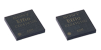
تکنولوژی EFFIO-V و EFFIO-A چیست؟

تکنولوژی EFFIO-V و EFFIO-A که توسط شرکت سونی به بازار عرضه شده اند با قابلیت و عملکردهای بسیار توسعه یافته به عنوان نسل سوم سری EFFIO در نظر گرفته می شود.

این دو محصول جدید میتوانند با سنسور تصویر 960H ترکیب شده تا بتوانند کیفیت تصویری بالاتر از 700 تی وی لاین را ایجاد نماید. همچنین این آی سی ها بهبود یافتند تا قابلیت هایی از قبیل کاهش نویز سه بعدی (3D-NR)و قرار گرفتن در معرض مادون قرمز و طیف گسترده ای پویا (WDR) و یا مه زدا DEFOG)) و نمایش تصاویر در شرایط مختلف مانند نور کم ، نور مادون قرمز و نور زیاد که کاملا توسعه یافته در عملکرد خود داشته باشند. علاوه بر این این آی سی ها برای اولین بار قابلیت تشخیص اتوماتیک به صورت صنعتی و انتخاب صحنه را دارا هستند.

EFFIO-V و EFFIO-A ، اصلاح شده تا پردازشگر سیگنال را با وضوح بالا انجام دهد و رزولوشن بالای 700تی وی لاین را ایجاد کند که این رزولوشن بالاتر از رزولوشن سری های EFFIOموجود 650 تی وی لاین است .

EFFIO-V و EFFIO-A

قابلیت کاهش نویز سه بعدی

این تکنولوژی تاری موضوعات در حال حرکت ، روشنی و سیگنال به نویز تصاویری که حتی در محیط های کم نور هستند را کاهش می دهد. همچنین به طور موثر از شرایط زمانی که انعکاس نور مادون قرمز بیش از حد شده باشد و یا جزئیات نفر پنهان شده باشد و یا زمانی که در اطراف لبه ای بیرونی تصاویر و یا گوشه های تاریک شده (سایه) باشد جلوگیری می کند.
بنابراین قابلیت این تکنولوژی بهبود بخشیدن تصاویر در محیط های کم نور می باشد.

این محصولات عملکرد مناسب در هر شرایطی برای تنظیم تصاویر را دارا هستند . بعضی از نصب ها زمان زیادی برای تنظیم چند دوربین با ویژگی های مختلف برای کیفیت بهتر را از ما می گیرند . اما EFFIO-V و EFFIO-A قابلیت تشخیص اتوماتیک صحنه را دارند و فقط نیاز به یک عملکرد برای 40الگو در صحنه های تصاویر را برای تصویری ایده آل مثل محدوده دینامیکی ، درجه حرارت ، رنگ را دارد. قابلیت انتخاب صحنه از پیش تنظیم شده برای صحنه های عمومی از جمله دوربین های محیط داخل و محیط خارج نصب شده یا نظارت ترافیکی و یا نور پس زمینه تنظیمات اتوماتیک آنها بر پایه تنظیمات برای کیفیت تصویر ایده آل می باشد .

این قابلیت تنظیمات اتوماتیک برای آسان تر شدن نصب و راه اندازی تصاویر با کیفیت است .


EFFIO-V و EFFIO-A


استفاده از EFFIO-V و EFFIO-A

استفاده از EFFIO-V و EFFIO-A


تاری در سایر ccd ها

سایر ccd ها


منبع

 
Item Effio-V Effio-A
Supported CCDs 760 H, 960 H WDR/normal CCD 760 H, 960 H normal CCD


Functions

Resolution Horizontal over 700 TV lines
WDR
ATR-EX2
Noise reduction 2D-NR, 3D-NR
Day & Night
Polygon privacy mask Up to 20 masks
E-zoom
Slow shutter
Digital image stabilizer
BLC/HLC
Automatic scene detection function
Scene selection function
AF detector
Motion detection
White pixel detection compensation Static and dynamic
OSD Flexible 8 languages
Lens shading compensation
Defog
Automatic mechanical iris adjustment
External synchronization LL, VSL
RS-485
Coaxial communication ✔ (Coaxitron by Pelco)
Outputs Analog outputs Y/C separate, composite
Digital outputs ITU-R BT.656 compliant
(27 MHz / 36 MHz)
Package 97-pin LFBGA

چرا از فضای رنگی مختلف استفاده می کنیم؟

از فضای رنگی مختلف استفاده می کنیم چون این امکان در آن فضای رنگی به ما داده میشه تا بتوینم رنگ دلخواه مان را به راحتی از محدوده دیگر رنگ ها جدا کنیم .فرض کنید که شما قصد دارید رنگ سبز را در تصویر فیلتر نمایید این بازه شامل طیفی می باشد که یک سمت آن سبز تیره و در سمت دیگر آن سبز روشن می باشد برای جدا کردن آن در فضای رنگی RGB این امکان وجود ندارد که شما بتوان به صورت خطی یعنی هر کانال با یک شرط بازه رنگ دلخواه را انتخاب نمائید پس به خاطر چنین مشکلاتی تصویر را به فضای رنگی HSV انتقال می دهیم که این فضا از اجزای Hue (رنگدانه) ،Saturation(اشباع) و Value(روشنایی) تشکیل شده.برای تفکیک رنگ سبز در این فضای رنگی کافیست محدوده Hue خود که مربوط به رنگ مورد نظر را انتخاب کرده و سپس کل محدوه اشباع و در نهایت انتخاب محدوده دلخواه برای روشنایی پس در این فضای رنگی به راحتی تونستید رنگ دلخواه خودتون را انتخاب کنید.

تبدیل فضای رنگی در opencv

در کتابخانه Opencv می تونیم از تابع cvtColor استفاده کنیم.

مثال:


/*------------------------------------------------------------------------------------------*\
This file contains material supporting chapter 3 of the cookbook:
Computer Vision Programming using the OpenCV Library
Second Edition
by Robert Laganiere, Packt Publishing, 2013.

This program is free software; permission is hereby granted to use, copy, modify,
and distribute this source code, or portions thereof, for any purpose, without fee,
subject to the restriction that the copyright notice may not be removed
or altered from any source or altered source distribution.
The software is released on an as-is basis and without any warranties of any kind.
In particular, the software is not guaranteed to be fault-tolerant or free from failure.
The author disclaims all warranties with regard to this software, any use,
and any consequent failure, is purely the responsibility of the user.

Copyright (C) 2013 Robert Laganiere, www.laganiere.name
\*------------------------------------------------------------------------------------------*/

#include <opencv2/core/core.hpp>
#include <opencv2/highgui/highgui.hpp>
#include <opencv2/imgproc/imgproc.hpp>

#include <iostream>
#include <vector>

void detectHScolor(const cv::Mat& image, // input image
double minHue, double maxHue, // Hue interval
double minSat, double maxSat, // saturation interval
cv::Mat& mask) { // output mask

// convert into HSV space
cv::Mat hsv;
cv::cvtColor(image, hsv, CV_BGR2HSV);

// split the 3 channels into 3 images
std::vector<cv::Mat> channels;
cv::split(hsv, channels);
// channels[0] is the Hue
// channels[1] is the Saturation
// channels[2] is the Value

// Hue masking
cv::Mat mask1; // under maxHue
cv::threshold(channels[0], mask1, maxHue, 255, cv::THRESH_BINARY_INV);
cv::Mat mask2; // over minHue
cv::threshold(channels[0], mask2, minHue, 255, cv::THRESH_BINARY);

cv::Mat hueMask; // hue mask
if (minHue < maxHue)
hueMask = mask1 & mask2;
else // if interval crosses the zero-degree axis
hueMask = mask1 | mask2;

// Saturation masking
// under maxSat
cv::threshold(channels[1], mask1, maxSat, 255, cv::THRESH_BINARY_INV);
// over minSat
cv::threshold(channels[1], mask2, minSat, 255, cv::THRESH_BINARY);

cv::Mat satMask; // saturation mask
satMask = mask1 & mask2;

// combined mask
mask = hueMask&satMask;
}

int main()
{
// read the image
cv::Mat image= cv::imread("boldt.jpg");
if (!image.data)
return 0;

// show original image
cv::namedWindow("Original image");
cv::imshow("Original image",image);

// convert into HSV space
cv::Mat hsv;
cv::cvtColor(image, hsv, CV_BGR2HSV);

// split the 3 channels into 3 images
std::vector<cv::Mat> channels;
cv::split(hsv,channels);
// channels[0] is the Hue
// channels[1] is the Saturation
// channels[2] is the Value

// display value
cv::namedWindow("Value");
cv::imshow("Value",channels[2]);

// display saturation
cv::namedWindow("Saturation");
cv::imshow("Saturation",channels[1]);

// display hue
cv::namedWindow("Hue");
cv::imshow("Hue",channels[0]);

// image with fixed value
cv::Mat newImage;
cv::Mat tmp(channels[2].clone());
// Value channel will be 255 for all pixels
channels[2]= 255;
// merge back the channels
cv::merge(channels,hsv);
// re-convert to BGR
cv::cvtColor(hsv,newImage,CV_HSV2BGR);

cv::namedWindow("Fixed Value Image");
cv::imshow("Fixed Value Image",newImage);

// image with fixed saturation
channels[1]= 255;
channels[2]= tmp;
cv::merge(channels,hsv);
cv::cvtColor(hsv,newImage,CV_HSV2BGR);

cv::namedWindow("Fixed saturation");
cv::imshow("Fixed saturation",newImage);

// image with fixed value and fixed saturation
channels[1]= 255;
channels[2]= 255;
cv::merge(channels,hsv);
cv::cvtColor(hsv,newImage,CV_HSV2BGR);

cv::namedWindow("Fixed saturation/value");
cv::imshow("Fixed saturation/value",newImage);

// Testing skin detection

// read the image
image= cv::imread("girl.jpg");
if (!image.data)
return 0;

// show original image
cv::namedWindow("Original image");
cv::imshow("Original image",image);

// detect skin tone
cv::Mat mask;
detectHScolor(image,
160, 10, // hue from 320 degrees to 20 degrees
25, 166, // saturation from ~0.1 to 0.65
mask);

// show masked image
cv::Mat detected(image.size(), CV_8UC3, cv::Scalar(0, 0, 0));
image.copyTo(detected, mask);
cv::imshow("Detection result",detected);

// A test comparing luminance and brightness

// create linear intensity image
cv::Mat linear(100,256,CV_8U);
for (int i=0; i<256; i++) {

linear.col(i)= i;
}

// create a Lab image
linear.copyTo(channels[0]);
cv::Mat constante(100,256,CV_8U,cv::Scalar(128));
constante.copyTo(channels[1]);
constante.copyTo(channels[2]);
cv::merge(channels,image);

// convert back to BGR
cv::Mat brightness;
cv::cvtColor(image,brightness, CV_Lab2BGR);
cv::split(brightness, channels);

// create combined image
cv::Mat combined(200,256, CV_8U);
cv::Mat half1(combined,cv::Rect(0,0,256,100));
linear.copyTo(half1);
cv::Mat half2(combined,cv::Rect(0,100,256,100));
channels[0].copyTo(half2);

cv::namedWindow("Luminance vs Brightness");
cv::imshow("Luminance vs Brightness",combined);

cv::waitKey();
}

منبع

مقدمه

حذف نویز تصاویر _ گروهی از محققان سیستمی را توسعه داده اند که با استفاده از هوش مصنوعی و بدون نیاز به عکس های واضح از منبع، نویز تصاویر را از بین می برد.

شرح خبر

این گروه متشکل از محققان انویدیا، MIT و دانشگاه آلتو در توسعه این سیستم از یادگیری عمیق بهره برده اند که بر خلاف روش های قبلی نیازی به مشاهده نمونه های کامل از تصویر مورد نظر داشته و تنها با استفاده از داده های ناقص یا دو تصویر غیر واضح به افزایش کیفیت تصاویر می پردازد. علاوه بر این نتیجه نهایی افزایش کیفیت، حذف متون یا اصلاح تصویر نسبت به روش های قبلی به مراتب بهتر است.

یادگیری عمیق گونه ای از یادگیری ماشینی است که در آن سیستم با کمک هوش مصنوعی نحوه بازیابی تصاویر دارای نویز از طریق کنار هم قرار دادن تصاویر، متون یا ویدیوها را فرا می گیرد. یکی دیگر از قابلیت های جالب توجه سیستم جدید افزایش کیفیت تصاویر در عرض چند میلی ثانیه است.
مبنای کار هوش مصنوعی در این سیستم بر شبکه عصبی استوار است که با استفاده از تصاویر دارای نویز آموزش دیده است. در این روش هوش مصنوعی علی رغم عدم نیاز به تصاویر واضح از منبع باید دوبار تصویر را مشاهده کند.

آزمایشات این گروه نشان داده که از تصاویر تخریب شده از طریق نویزهایی نظیر «گاوسی افزایشی»، «پواسون» یا ترکیب آنها می توان برای تولید تصاویر بهینه ای استفاده کرد که کیفیت آن‌ها با تصاویر بازیابی‌ شده از عکس های بدون مشکل تقریبا برابر است.
کاربردهای علمی این سیستم مبتنی بر یادگیری عمیق شامل زمینه های پزشکی است که در آن می توان کیفیت اسکن های MRI و تصاویر دیگر را به شکل چشمگیری افزایش داد.

چند ماه قبل نیز تیم تحقیقاتی انستیتوی «ماکس پلانک» به رهبری دکتر مهدی سجادی، الگوریتمی را توسعه داده بودند که با بهره گیری از هوش مصنوعی وضوح تصاویر بی کیفیت را تا حد زیادی بهبود می بخشید.

کد برنامه تشخیص و شمارش خودروهای در حال حرکت در زبان Matlab

در این پروژه سعی داریم با استفاده از روش «رهگیری اهداف چندگانه» اقدام به شناسایی اشیاء در حال حرکت نموده و آنها را شمارش نمائیم. این برنامه می تواند جهت شمارش تعداد خودروهای عبوری، تعداد افراد در حال تردد و… مورد استفاده قرار بگیرد. این الگوریتم توسط شرکت mathwork پیاده سازی گردیده و جهت استفاده علاقه مندان ادامه ارائه می گردد.

باتوجه به توضیحات کامل این پروژه از ذکر توضیحات اضافه اجتناب میکنیم و فقط شرحی مختصر از عماکرد برنامه ارائه می نماییم. ابتدا با استفاده از چند فریم به عنوان نمونه، زمینه(background) را شناسایی می کنیم و سپس به اقدام به تشخیص آبجکت های(foreground) می نماییم. سپس با استفاده از روش کالمن (Kalman) اقدام به رهگیری آبجکت هایی که از مقداری مشخص (اصلاحا blob) بزرگتر هستند می نمائیم.  در ادامه آبجکت ها را رهگیری می کنیم تا هنگامی که از صفحه خارج شوند. نکته جالب توجه این هست که اگر آبجکتی موقتا ناپیدا شود(مثلا زیر پل یا درخت قرار بگیرد) به عنوان «Predicted» برچسب خورده و پس از پیدا شدن مجددا به عنوان همان آبجکت قبلی شناسایی می شود.


تشخیص و شمارش خودروهای در حال حرکت

سورس کد برنامه تشخیص و شمارش خودرو:


%% Multiple Object Tracking Tutorial
% This example shows how to perform automatic detection and motion-based
% tracking of moving objects in a video. It simplifies the example
% <matlab:helpview(fullfile(docroot,'toolbox','vision','vision.map'),'MotionBasedMultiObjectTrackingExample')
% Motion-Based Multiple Object Tracking> and uses the |multiObjectTracker|
% available in Automated Driving System Toolbox.
%
% Copyright 2016 The MathWorks, Inc.
 
%%
% Detection of moving objects and motion-based tracking are important 
% components of many computer vision applications, including activity
% recognition, traffic monitoring, and automotive safety. The problem of
% motion-based object tracking can be divided into two parts:
%
% # Detecting moving objects in each frame 
% # Tracking the moving objects from frame to frame 
%
% The detection of moving objects uses a background subtraction algorithm
% based on Gaussian mixture models. Morphological operations are applied to
% the resulting foreground mask to eliminate noise. Finally, blob analysis
% detects groups of connected pixels, which are likely to correspond to
% moving objects. 
%
% The tracking of moving objects from frame to frame is done by the
% |multiObjectTracker| object that is responsible for the following:
%
% # Assigning detections to tracks. 
% # Initializing new tracks based on unassigned detections. All tracks are
% initialized as |'Tentative'|, accounting for the possibility that they
% resulted from a false detection.
% # Confirming tracks if they have more than _M_ assigned detections in _N_
% frames.
% # Updating existing tracks based on assigned detections.
% # Coasting (predicting) existing unassigned tracks.
% # Deleting tracks if they have remained unassigned (coasted) for too long.
%
% The assignment of detections to the same object is based solely on
% motion. The motion of each track is estimated by a Kalman filter. The
% filter predicts the track's location in each frame, and determines the
% likelihood of each detection being assigned to each track. To initialize
% the filter that you design, use the |FilterInitializationFcn| property of
% the |multiObjectTracker|.
%
% For more information, see
% <matlab:helpview(fullfile(docroot,'toolbox','vision','vision.map'),'multipleObjectTracking') Multiple Object Tracking>.
%
% This example is a function, with the main body at the top and helper 
% routines in the form of 
% <matlab:helpview(fullfile(docroot,'toolbox','matlab','matlab_prog','matlab_prog.map'),'nested_functions') nested functions> 
% below.
 
function p12_on_video_using_tracking_matlab_sample()
% Create objects used for reading video and displaying the results.
videoObjects = setupVideoObjects('6.mp4');
 
% Create objects used for detecting objects in the foreground of the video.
minBlobArea = 10000; % Minimum blob size, in pixels, to be considered as a detection
detectorObjects = setupDetectorObjects(minBlobArea);
 
%% Create the Multi-Object Tracker
% When creating a |multiObjectTracker|, consider the following: 
%
% # |FilterInitializationFcn|: The likely motion and measurement models. 
% In this case, the objects are expected to have a constant speed motion.
% The |initDemoFilter| function configures a linear Kalman filter to 
% track the motion. See the 'Define a Kalman filter' section for details.
% # |AssignmentThreshold|: How far detections may fall from tracks. 
% The default value for this parameter is 30. If there are detections
% that are not assigned to tracks, but should be, increase this value. If
% there are detections that get assigned to tracks that are too far,
% decrease this value.
% # |NumCoastingUpdates|: How long a track is maintained before deletion.
% In this case, since the video has 30 frames per second, a reasonable
% value is about 0.75 seconds (22 frames).
% # |ConfirmationParameters|: The parameters controlling track confirmation.
% A track is initialized with every unassigned detection. Some of these
% detections might be false, so initially, all tracks are |'Tentative'|. 
% To confirm a track, it has to be detected at least _M_ out of _N_
% frames. The choice of _M_ and _N_ depends on the visibility of the
% objects. This example assumes a visibility of 6 out of 10 frames.
tracker = multiObjectTracker(...
 'FilterInitializationFcn', @initDemoFilter, ...
 'AssignmentThreshold', 30, ...
 'NumCoastingUpdates', 22, ...
 'ConfirmationParameters', [6 10] ...
 );
 
%% Define a Kalman Filter
% When defining a tracking filter for the motion, complete the following
% steps:
%
% *Step 1: Define the motion model and state*
%
% In this example, use a constant velocity model in a 2-D rectangular
% frame.
%
% # The state is |[x;vx;y;vy]|.
% # The state transition model matrix is |A = [1 dt 0 0; 0 1 0 0; 0 0 1 dt; 0 0 0 1]|.
% # Assume that |dt = 1|.
%
% *Step 2: Define the process noise*
%
% The process noise represents the parts of the process that are not taken
% into account in the model. For example, in a constant velocity model, the
% acceleration is neglected.
%
% *Step 3: Define the measurement model*
%
% In this example, only the position (|[x;y]|) is measured. So, the
% measurement model is |H = [1 0 0 0; 0 0 1 0]|.
%
% Note: To preconfigure these parameters, define the |'MotionModel'|
% property as |'2D Constant Velocity'|.
%
% *Step 4: Initialize the state vector based on the sensor measurement*
%
% In this example, because the measurement is |[x;y]| and the state is
% |[x;vx;y;vy]|, initializing the state vector is straightforward. Because
% there is no measurement of the velocity, initialize the |vx| and |vy|
% components to 0.
%
% *Step 5: Define an initial state covariance*
%
% In this example, the measurements are quite noisy, so define the initial 
% state covariance to be quite large: |stateCov = diag([50, 50, 50, 50])|
%
% *Step 6: Create the correct filter*
% 
% In this example, all the models are linear, so use |trackingKF| as the
% tracking filter.
 function filter = initDemoFilter(detection)
 % Initialize a Kalman filter for this example.
 
 % Define the initial state.
 state = [detection.Measurement(1); 0; detection.Measurement(2); 0];
 
 % Define the initial state covariance.
 stateCov = diag([50, 50, 50, 50]);
 
 % Create the tracking filter.
 filter = trackingKF('MotionModel', '2D Constant Velocity', ... 
 'State', state, ...
 'StateCovariance', stateCov, ... 
 'MeasurementNoise', detection.MeasurementNoise(1:2,1:2) ... 
 );
 end
 
%%% 
% The following loop runs the video clip, detects moving objects in the
% video, and tracks them across video frames. 
 
% Count frames to create a sense of time.
frameCount = 0;
while hasFrame(videoObjects.reader)
 % Read a video frame and detect objects in it.
 frameCount = frameCount + 1; % Promote frame count
 frame = readFrame(videoObjects.reader); % Read frame 
 [detections, mask] = detectObjects(detectorObjects, frame); % Detect objects in video frame 
 
 % Run the tracker on the preprocessed detections.
 confirmedTracks = updateTracks(tracker, detections, frameCount);
 
 % Display the tracking results on the video.
 displayTrackingResults(videoObjects, confirmedTracks, frame, mask);
end
%% Create Video Objects
% Create objects used for reading and displaying the video frames.
 
 function videoObjects = setupVideoObjects(filename)
 % Initialize video I/O
 % Create objects for reading a video from a file, drawing the tracked
 % objects in each frame, and playing the video.
 
 % Create a video file reader.
 videoObjects.reader = VideoReader(filename);
 
 % Create two video players: one to display the video,
 % and one to display the foreground mask. 
 videoObjects.maskPlayer = vision.VideoPlayer('Position', [20, 400, 700, 400]);
 videoObjects.videoPlayer = vision.VideoPlayer('Position', [740, 400, 700, 400]);
 end
 
%% Create Detector Objects
% Create objects used for detecting foreground objects.
% Use |minBlobArea| to define the size of the blob, in pixels, that is
% considered to be a detection. 
%
% * Increase |minBlobArea| to avoid detecting small blobs, which are more
% likely to be false detections, or if several detections are created for 
% the same object due to partial occlusion.
% * Decrease |minBlobArea| if objects are detected too late or not at all.
 
 function detectorObjects = setupDetectorObjects(minBlobArea)
 % Create System objects for foreground detection and blob analysis
 
 % The foreground detector segments moving objects from the
 % background. It outputs a binary mask, where the pixel value of 1
 % corresponds to the foreground and the value of 0 corresponds to
 % the background.
 
 detectorObjects.detector = vision.ForegroundDetector('NumGaussians', 3, ...
 'NumTrainingFrames', 40, 'MinimumBackgroundRatio', 0.7);
 
 % Connected groups of foreground pixels are likely to correspond to
 % moving objects. The blob analysis System object finds such
 % groups (called 'blobs' or 'connected components') and computes
 % their characteristics, such as their areas, centroids, and the
 % bounding boxes.
 
 detectorObjects.blobAnalyzer = vision.BlobAnalysis('BoundingBoxOutputPort', true, ...
 'AreaOutputPort', true, 'CentroidOutputPort', true, ...
 'MinimumBlobArea', minBlobArea);
 end
 
%% Detect Objects
% The |detectObjects| function returns the centroids and the bounding boxes
% of the detected objects as a list of |objectDetection| objects. You can
% supply this list as an input to the |multiObjectTracker|. The
% |detectObjects| function also returns the binary mask, which has the same
% size as the input frame. Pixels with a value of 1 correspond to the
% foreground. Pixels with a value of 0 correspond to the background.
%
% The function performs motion segmentation using the foreground detector. 
% It then performs morphological operations on the resulting binary mask to
% remove noisy pixels and to fill the holes in the remaining blobs.
%
% When creating the |objectDetection| list, the |frameCount| serves as the
% time input, and the centroids of the detected blobs serve as the
% measurement. The list also has two optional name-value pairs:
%
% * |MeasurementNoise| - Blob detection is noisy, and this example defines 
% a large measurement noise value.
% * |ObjectAttributes| - The detected bounding boxes that get passed to the
% track display are added to this argument.
 
 function [detections, mask] = detectObjects(detectorObjects, frame)
 % Expected uncertainty (noise) for the blob centroid.
 measurementNoise = 100*eye(2); 
 % Detect foreground.
 mask = detectorObjects.detector.step(frame);
 
 % Apply morphological operations to remove noise and fill in holes.
 mask = imopen(mask, strel('rectangle', [9, 9]));
 mask = imclose(mask, strel('rectangle', [10, 10])); 
 mask=bwareaopen(mask,1500);
 mask = imfill(mask, 'holes');
 
 % Perform blob analysis to find connected components.
 [~, centroids, bboxes] = detectorObjects.blobAnalyzer.step(mask);
 
 % Formulate the detections as a list of objectDetection objects.
 numDetections = size(centroids, 1);
 detections = cell(numDetections, 1);
 for i = 1:numDetections
 detections{i} = objectDetection(frameCount, centroids(i,:), ...
 'MeasurementNoise', measurementNoise, ...
 'ObjectAttributes', {bboxes(i,:)});
 end
 end
 
%% Display Tracking Results
% The |displayTrackingResults| function draws a bounding box and label ID
% for each track on the video frame and foreground mask. It then displays
% the frame and the mask in their respective video players.
 
 function displayTrackingResults(videoObjects, confirmedTracks, frame, mask)
 % Convert the frame and the mask to uint8 RGB.
 frame = im2uint8(frame);
 mask = uint8(repmat(mask, [1, 1, 3])) .* 255;
 
 if ~isempty(confirmedTracks) 
 % Display the objects. If an object has not been detected
 % in this frame, display its predicted bounding box.
 numRelTr = numel(confirmedTracks);
 boxes = zeros(numRelTr, 4);
 ids = zeros(numRelTr, 1, 'int32');
 predictedTrackInds = zeros(numRelTr, 1);
 for tr = 1:numRelTr
 % Get bounding boxes.
 boxes(tr, : ) = confirmedTracks(tr).ObjectAttributes{1}{1};
 
 % Get IDs.
 ids(tr) = confirmedTracks(tr).TrackID;
 
 if confirmedTracks(tr).IsCoasted
 predictedTrackInds(tr) = tr;
 end
 end
 
 predictedTrackInds = predictedTrackInds(predictedTrackInds > 0);
 
 % Create labels for objects that display the predicted rather 
 % than the actual location.
 labels = cellstr(int2str(ids));
 
 isPredicted = cell(size(labels));
 isPredicted(predictedTrackInds) = {' predicted'};
 labels = strcat(labels, isPredicted);
 
 % Draw the objects on the frame.
 frame = insertObjectAnnotation(frame, 'rectangle', boxes, labels);
 
 % Draw the objects on the mask.
 mask = insertObjectAnnotation(mask, 'rectangle', boxes, labels);
 end
 
 % Display the mask and the frame.
 videoObjects.maskPlayer.step(mask); 
 videoObjects.videoPlayer.step(frame);
 end
displayEndOfDemoMessage(mfilename)
end
%% Summary
% In this example, you created a motion-based system for detecting and
% tracking multiple moving objects. Try using a different video to see if
% you can detect and track objects. Try modifying the parameters of the
% |multiObjectTracker|.
%
% The tracking in this example was based solely on motion, with the
% assumption that all objects move in a straight line with constant speed.
% When the motion of an object significantly deviates from this model, the
% example can produce tracking errors. Notice the mistake in tracking the
% person occluded by the tree.
%
% You can reduce the likelihood of tracking errors by using a more complex
% motion model, such as constant acceleration or constant turn. To do that,
% try defining a different tracking filter, such as |trackingEKF| or
% |trackingUKF|. 

تشخیص و شمارش خودروهای در حال حرکت


منبع:

https://www.mathworks.com/


جهت دانلود بر روی لینک زیر کلیک نمایید.

تشخیص و شمارش خودروهای درحال حرکت

ویدئوی پیوست برنامه تشخیص و شمارش خودورهای در حال حرکت

رمز فایل : behsanandish.com


رباتیک

رباتیک شاخه ای میان رشته ای از مهندسی و علم است که شامل مهندسی مکانیک ، مهندسی برق و علوم رایانه و چند رشته دیگر می‌شود . رباتیک شامل طراحی ، ساخت ، راه اندازی و استفاده از رباتها می شود، همچنین مانند سیستم های رایانه ای ، کنترل ، بازخورد حسگرها و پردازش اطلاعات نیز در این گروه قرار می گیرند.

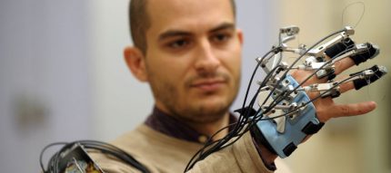
سیستم دست رباتی سایه

سیستم دست رباتی سایه

ایده ایجاد ماشینهایی که بتوانند به شکل خودکار کار کنند ، به دوران قدیم بازمی گردد ولی تحقیق اساسی در مورد به کاربرد رساندن و استفاده های بالقوه از رباتها تا قرن بیستم انجام نشده بود. در طول تاریخ بارها خاطر نشان شده است که یک روز رباتها خواهند توانست رفتار انسانها را تقلید کنند و کارها را به شیوه مشابه انسان انجام دهند . امروزه رباتیک یک حوزه از علم با رشد سریع است. ، همزمان با ادامه پیشربتهای تکنولوژی ؛ تحقیق ، طراحی و ساخت رباتهای جدید در خدمت اهداف عملی متعددی در حوزه های خانگی ، صنعتی و نظامی انجام می گیرد. بسیاری از رباتها برای انجام شغلهای خطرناک برای مردم انجام وظیفه می کنند ، مانند کار کردن در خنثی سازی بمب ، یافتن بازمانده های زیر آوارهای غیر پایدار ، مین یابی یا جستجوی کشتی های غرق شده .

رباتیک همچنین به عنوان یک هدف آموزشی در مجموعه چند گانه علم ، تکنولوژی ، مهندسی و ریاضی نیز به کار می رود.

ریشه شناسی

رباتیک از کلمه ربات مشتق شده است . خود کلمه ربات برای اولین بار توسط نویسنده ای از اهالی چکسلواکی به نام کارل چاپک و در نمایشنامه ای به اسم کارخانه ربات سازی روسوم در سال 1920 معرفی شد. کلمه روبات از واژه اسلاوی ” روبوتا ” به دست آمده است که در اصل به معنی کارگر به کار می رود. نمایشنامه در مورد یک کارخانه است که آدم های مصنوعی به نام ربات ها تولید می کند ؛ موجوداتی که می توانند با انسانها اشتباه گرفته شوند و این بسیار مشابه ایده های مدرن امروزی در مورد انسان نماها است. کارل چاپک این کلمه را متعلق به خودش نمی داند ، وی یک نامه کوتاه به قسمت ریشه شناسی لغات در فرهنگ انگلیسی آکسفورد نوشته است که در آن برادرش جوزف چاپک را به عنوان ابداع کننده اصلی این کلمه نام برده است.

مطابق فرهنگ انگلیسی آکسفورد کلمه رباتیک اولین بار در نوشته ای توسط آیزاک آسیموف ، در قسمتی از یک داستان کوتاه علمی تخیلی به نام “دروغگو” به کار برده شد. این داستان اولین بار در مجله علمی تخیلی استوندینگ چاپ شد. در آن هنگام آسیموف خودش نمی دانست که این کلمه به نام او ثبت خواهد شد ؛ وی فکر می کرد همان گونه که علم و تکنولوژی مربوط به وسایل الکترونیکی را الکترونیک می نامند ، پس رباتیک به علم و تکنولوژی مربوط به رباتها اشاره خواهد داشت . آسیموف در بعضی از آثارش خاطر نشان می کند که اولین کاربرد کلمه رباتیک در داستان کوتاه او به نام “سرگردانی” ( مجله علمی تخیلی استوندینگ ، مارس 1942 ) بوده است ولی باید توجه کرد که چاپ اصلی داستان “دروغگو” ده ماه پیش از “سرگردانی” بوده است ، بنابراین عموما داستان قدیمی تر به عنوان منشا کلمه شناخته می شود.

منبع


رباتیک، علمی با هدف راحتی انسان

اگر فردی علاقه‌مند به تکنولوژی هستید یا اخبار روز دنیا را در زمینه‌های مختلف علمی دنبال می‌کنید، حتما متوجه شده‌اید، همان گونه که امروزه ربات‌ها در بسیاری از مسائل مانند: ” صنعت، پزشکی، آتش نشانی ، حتی در خانه‌ها و ...”  به کمک انسان‌ها امده و بسیاری از مشکلات را حل کرده است، تاثیر وسیعی در زندگی آینده انسان‌ها خواهند داشت.

امروزه همان طور که شاهد آن هستیم، خانواده‌ها چه در ایران و چه در خارج کشور فرزند خود را تشویق به حضور در کلاس‌های رباتیک و ساخت ربات‌ها می‌کنند و همچنین مسابقات ربات‌ها که در زمینه‌های مختلفی به انجام می‌رسد، با استقبال خوب و رو به رشدی از سوی اکثر کشورها مواجه می‌شود.همچنین رشته‌ی دانشگاهی مهندسی رباتیک و هوش مصنوعی در خارج از کشور با استقبال خوبی از سوی علاقه مندان به این حوزه رو به رو است و زمینه‌های تحقیقاتی و کاری فراوانی برای مهندسین و فارغ التحصیلان این رشته تدارک دیده اند، زیرا  این موضوع برای آن‌ها روشن است، که زندگی امروز و فردا‌ی ما، جدا از ربات‌ها امکان پذیر نیست.

برای آشنایی بیشتر با هوش مصنوعی میتوانید به نوشته هوش مصنوعی چیست مراجعه نمایید.


رباتیک-تکنولوژی


دکتر  کارو لوکاس قوکاسیان ، دانشمند برجسته ایرانی و از پژوهشگران به‌ نام سیستم‌های هوشمند در ایران بود. زمینه‌ی پژوهش‌های او پیش‌بینی سری‌های زمانی، مدل‌های عاطفی و منطق فازی است. وی همچنین به عنوان «پدر علم رباتیک ایران» شناخته می‌شود.صحبت‌های ایشان در زمینه رباتیک این جمله را تصدیق می‌کند که :

یکی از مهم‌ترین دستاوردهای علمی بشر، علم رباتیک است که با رشد روز افزون دانش بشری، بیشتر وارد زندگی انسان‌ها شده و آن‌ را دست‌خوش تغییر می‌کند. 

رباتیک دقیقا یعنی چه؟

رباتیک علم مطالعه فن آوری مرتبط با طراحی ساخت و اصول کلی و کاربرد ربات‌ها است، که با هدف راحتی انسان و افزایش وقت مفید او به وجود آمده است، به عبارت دیگر رباتیک علم و فن آوری ماشین‌های قابل برنامه ریزی، با کاربردهای عمومی می‌باشد.

هر دستگاه الکترومکانیکی که عمل خاصی را انجام دهد ربات نامیده می‌شود که می‌تواند جهت انجام یک وظیفه خاص برنامه ریزی شود.

کلمه ربات اولین بار توسط Karel Capek  نویسنده نمایشنامه R.U.R روبات‌های جهانی روسیه در سال ۱۹۲۱ ابداع شد. ریشه این کلمه، کلمه چک اسلواکی (robotnic) به معنی کارگر می‌باشد. تفاوت ربات با انسان از بسیاری جهات قابل چشم پوشی نیست. مثلا خستگی ناپذیری و انجام یک کار تکراری با دقت فراوان و یا کارهایی که توان زیادی نیاز دارند و بازوهای انسان توان لازم برای انجام آن را ندارند به راحتی از عهده ربات‌ها بر می‌آید.

ربات‌ها می‌توانند بسیار ساده و یا با ساختاری پیچیده باشند ولی در همه حالت‌ها ربات، ترکیب علوممکانیک و الکترونیک است.

برخلاف تصور  عمومی از ربات‌ها که به عنوان ربات‌های انسان نما که تقریباً قابلیت انجام هر کاری را دارند، بیشتر دستگاه‌های رباتیک در مکان‌های ثابتی در کارخانه‌ها بسته شده اند و در فرایند ساخت با کمک کامپیوتر، اعمال قابل انعطاف، ولی محدودی را انجام می‌دهند.این دستگاه  حداقل شامل یک کامپیوتر برای نظارت بر اعمال و عملکرد  اسباب انجام دهنده عمل مورد نظر  و همچنین ممکن است دارای حسگرها و تجهیزات جانبی باشد.

انواع ربات‌ها

 احتمالا این سوال برایتان به‌وجود آمده که ایده اصلی ساخت ربات‌ها چگونه شکل می گیرد و هر ربات از چه قسمت‌هایی تشکیل شده است.

دو نکته در به وجود آمدن و ایده اصلی ربات اهمیت دارد، ابتدا اینکه یک مشکل یا سختی کار وجود دارد و باید حل گردد. دوم اینکه در طبیعت موجودی آن را حل کرده یا نه؟ مثلا تونل زدن زیر خاک یک مشکل بیان می‌گردد. و در طبیعت یک کرم کوچولو به راحتی می‌تواند زیر خاک حرکت نماید این دو باعث طراحی و ساخت یک ربات می‌گردد که به صورت اتوماتیک تونل کنده و پیش می‌رود.

ربات‌ها همانند کامپیوترها قابلیت برنامه ریزی دارند.بسته به نوع برنامه‌ای که شما به آن‌ها می‌دهید، کارها وحرکات مختلفی را انجام می‌دهند. رشته‌ی دانشگاهی نیز تحت عنوان رباتیک وجود دارد که به مسائلی از قبیل: “سنسورها، مدارات ، فیدبک‌ها،پردازش اطلاعات و بست و توسعه ربات‌ها” می‌پردازد.ربات‌ها انواع مختلفی دارند از قبیل: “روبات‌های شمشیر باز، ربات دنبال کننده خط یا مسیریاب، کشتی گیر، فوتبالیست، ربات‌های پرنده و ربات‌های خیلی ریز تحت عنوان «میکرو ربات‌ها» و «نانو ربات‌ها»  نیز وجود دارند. ربات‌ها برای انجام کارهای سخت و دشواری  که بعضی مواقع انسان‌ها از انجام آن‌ها عاجز یا انجام آن‌ها برای انسان خطرناک هستند; مثل: “ربات‌هایی که در نیروگاه‌های هسته‌ای وجود دارند” ،استفاده می‌شوند.کاری که ربات‌ها انجام می‌دهند، توسط میکرپروسسورها (microprocessors) و میکرو کنترل‌ها(microcontroller) کنترل می‌شود.

شما با تسلط در برنامه نویسی میکرو پروسسورها و میکروکنترل‌ها، می‌توانید دقیقا به ربات بگویید همان کاری را که انتظار دارید، انجام دهد.


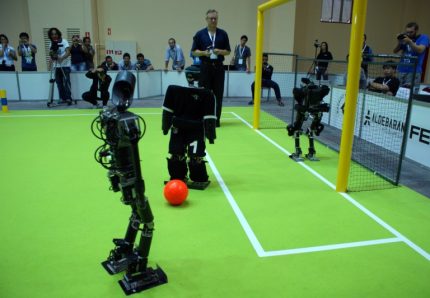
رباتیک-ربات فوتبالیست


بعضی از ربات‌ها، ماشین‌های مکانیکی نسبتاً ساده‌ای هستند که کارهای اختصاصی مانند جوشکاری و یا رنگ افشانی را انجام می‌دهند، که سایر سیستم‌های پیچیده تر که بطور همزمان چند کار انجام می‌دهند، از دستگاههای حسی، برای جمع آوری اطلاعات مورد نیاز برای کنترل کارشان نیاز دارند.حسگرهای یک ربات ممکن است بازخورد حسی ارائه دهند، طوریکه بتوانند اجسام را برداشته و بدون آسیب زدن، در جای مناسب قرار دهند. ربات دیگری ممکن است دارای نوعی دید باشد.، که عیوب کالاهای ساخته شده را تشخیص دهد. بعضی از ربات‌های مورد استفاده در ساخت مدارهای الکترونیکی، پس از مکان یابی دیداری علامت‌های تثبیت مکان بر روی برد، می‌توانند اجزا بسیار کوچک را در جای مناسب قرار دهند.

ربات‌ها دارای سه قسمت اصلی هستند:

۱. مغز که معمولا یک کامپیوتر است.

۲. محرک و بخش مکانیکی شامل موتور، پیستون، تسمه، چرخ‌ها، چرخ‌دنده‌ها و …

۳. سنسور که می‌تواند از انواع بینایی، صوتی، تعیین دما، تشخیص نور و تماسی یا حرکتی باشد.


رباتیک-ربات های خط تولید


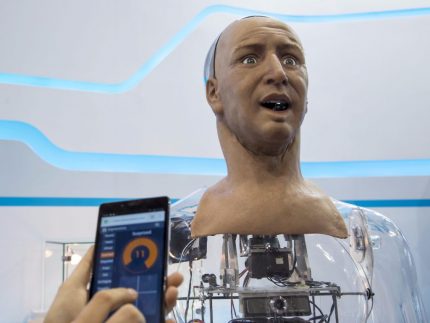
ربات‌هایی که امروزه بسیار  در حال تکاملند، ربات‌های انسان نما  (human robotic) هستند، آن‌ها قادرند اعمالی شبیه انسان را انجام دهند.حتی بعضی از آن‌ها همانند انسان دارای احساسات نیز هستند.برخی دیگر اشکال خیلی ساده‌ای دارند.آن‌ها دارای چرخ یا بازویی هستند که توسط میکروکنترلرها یا میکروپروسسورها کنترل می‌شوند.در واقع میکروکنترلر یا میکرو پروسسور به مانند مغز انسان در ربات کار می‌کند.برخی از ربات‌ها مانند انسان‌ها وجانوران خون گرم در برخورد و رویارویی با حوادث و مسائل مختلف به صورت هوشمند از خود واکنش نشان می‌دهند.یک نمونه از این ربات‌ها، ربات مامور است.


رباتیک-ربات شبه انسان


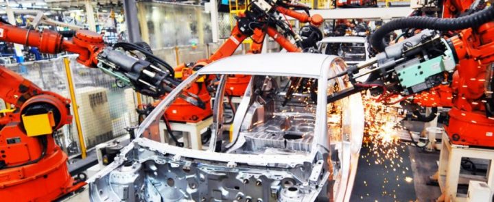
برخی ربات‌ها نیز یکسری کارها را به صورت تکراری با سرعت و دقت بالا انجام می‌دهند، مثل ربات‌هایی که در کارخانه‌های خودرو‌سازی استفاده می‌شوند.این گونه ربات‌ها، کارهایی از قبیل جوش دادن بدنه ماشین ، رنگ کردن ماشین را با دقتی بالاتر از انسان بدون خستگی و وقفه انجام می‌دهند.بیشتر ربات‌ها امروزه در کارخانه‌ها برای ساخت محصولاتی مانند اتومبیل؛ الکترونیک و همچنین برای اکتشافات زیرآب یا در سیارات دیگر مورد استفاده قرار می‌گیرد.


مکاترونیک-ربات صنعتی

بازار کار مهندس رباتیک

همان‌طور که در قبل گفته شد، پیش بینی می‌شود که رباتیک یکی از ۱۰ صنعت برتر آینده باشد. کاربرد محصولات رباتیک از محدوده کارخانجات فراتر رفته و در حال ورود به کاربردهای روزمره است.

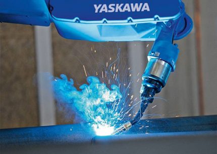
امروزه کمتر صنعتی را می‌توان یافت که در آن از ربات استفاده نشود . بازوهای رباتیکی که بدون استراحت قطعات و محصولات را از نقطه‌ای به نقطه‌ی دیگر جا‌به‌جا می‌کنند، ربات‌های جوشکار ، ربات‌های رنگرز ، ربات‌های بسته بند ، ربات‌های تراشکار ، ربات‌های چاپگر ، ربات‌های کنترل کیفیت ، ربات‌های سوراخکار ، ربات‌های کنترل دما ، ربات‌های هشداردهنده‌ی نشت گاز ، ربات‌های غربال ، سانتریفوژهای خودکار و … همگی نمونه‌هایی از ربات‌ها در کارخانه‌ها هستند.کارخانجات برای افزایش سرعت و کیفیت و دقت و هزینه‌ی پایین تر به سمت رباتیکی کردن تمامی قسمت‌های کارخانه پیش می‌روند و در بعضی از قسمت‌ها که برای انسان خطرناک است مانند جوشکاری و رنگ پاشی و سموم شیمیایی ناچار به استفاده از ربات می‌شوند.


رباتیک-ربات‌جوشکار


مهندسی رباتیک ارتباط زیادی با مهندسی مکانیک، مهندسی کامپیوتر و مهندسی الکترونیک و علوم کامپیوتر دارد. مهندس رباتیک باید برای ساخت روبات‌ها در این علوم مهندسی مرتبط مسلط باشد به عنوان مثال باید در برنامه نویسی و تنظیم الگوریتم بهینه، طراحی مدارهای الکتریکی و الکترونیکی، طراحی کامپیوتری مدارها، طراحی سیستم آیرودینامیکی و … تبحر و تسلط کافی داشته باشد. مهندس رباتیک به کسب و کارهای مختلف راه حل‌های خودکار و اتوماتیک ارائه می‌کند تا بتوانند کارآمدتر کار کنند. کار دیگر مهندس رباتیک رفع مشکلات موجود در برنامه‌های ربات‌ها و ارائه خدمات فنی به مشتریان است.

رباتیک با مکاترونیک تفاوت های بسیاری دارد که در مقاله مهندسی مکاترونیک می‌توانید جزییات آن را مطالعه نمایید.

مهندس رباتیک فردی است که پاسخگوی  نیاز صنعت در تحقیق و توسعه، طراحی، تولید، نگهداری و تعمیرات ربات‌ها می‌باشد.

یکی از شاخه‌های اصلی مهندسی رباتیک را میتوان بخش تحقیقات دانست. بنابراین در بخش رباتیک به متخصصانی نیاز است که تحقیقات کرده ، مفاهیم و کاربردهای جدید را یافته و راه‌های پیشرفت مفاهیم و کاربردهای موجود را بیابند. می‌توان گفت مهندسی رباتیک زمینه‌ای جذاب برای آنانی است که در حوزه تکنولوژی علاقه و استعداد خوبی دارند.

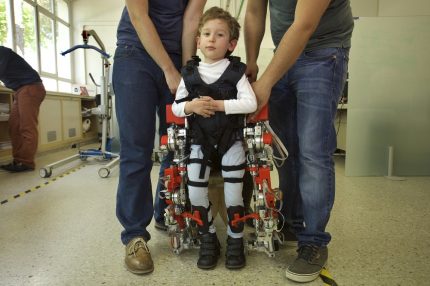
کار مهندس رباتیک، تحقیق و توسعه طرح‌ها، ساخت نمونه روبات‌ها و بررسی کاربردهای مختلف آن‌ها از حوزه‌های نظامی و خودرو تا حوزه پزشکی و کمک به افراد ناتوان برای رفع مشکلاتشان می‌باشد. همچنین مهندس رباتیک، ربات‌های موجود و توانمندی‌هایشان را ارتقا داده و اصلاحات لازم را روی آن‌ها انجام می‌دهد.


رباتیک-بیو‌مکاترونیک

آینده شغلی مهندس رباتیک

مهندس رباتیک می‌تواند در دو حوزه‌ صنعت و  آموزش و پژوهش مشغول به کار شود. صنایع خودرو، هوافضا، تولید تجهیزات الکترونیکی، هسته‌ای، معدن، نساجی، کامپیوتر، کشاورزی و … نمونه‌هایی از حوزه‌ی صنعت هستند. علاقه‌مندان به مشاغل آموزشی وپژوهشی می‌توانند با کسب مدارک عالی در این حوزه، در دانشگاه‌ها و مراکز آموزش عالی تدریس کنند. از آن‌جایی که مهندسی رباتیک رشته‌ای نوپا در کشورمان ایران می‌باشد، فرصت‌های شغلی خوبی در بخش آموزش عالی وجود دارد.

امروزه بسیاری از صنایع کشور از جمله کارخانه‌هایی مانند فولاد ، خودروسازی ، مواد غذایی و … تقریبا تمام اتوماتیک هستند. اما متاسفانه تمام ربات‌های آن وارداتی است و حتی در برخی  موارد نصب و کنترل و تعمیر آن‌ها بر عهده‌ی متخصصان خارجی می‌باشد. شرکت‌های فعال داخلی در حوزه رباتیک صرفا به واردات و در برخی از موارد تعمیرات روبات‌ها می‌پردازند.

علیرغم شرکت فعال گروه‌های دانش آموزی و دانشجویی در مسابقات مختلف رباتیک و کسب مقام‌های برتر، توجه کافی و هدفمند به استفاده ازاین نیروها در صنایع و بخش‌های مختلف کشور برای طراحی، تولید و تعمیر و نگهداری داخلی ربات‌های مورد نیاز نمی‌شود. در سال‌های قبل این مسابقات فقط در حد کسب یک مقام بوده ، نه ارتباطی با صنایع کشور داشته و نه تاثیری در تبدیل کردن ایران به یکی از قطب‌های رباتیک ایران. کشوری مثل ژاپن که به صورت فعال در بحث تحقیقات رباتیک کار می‌کند و به دنبال ساخت روبات‌های انسان نما است، از لحاظ صنعتی و تولید ربات نیز بسیار پیشرفت کرده است تا جایی که یکی از بزرگترین صادرکننده‌های ربات در جهان می‌باشد.

رباتیک-مسابقات


از دیگر مشکلاتی که در این حوزه وجود دارد، عدم شناخت و آگاهی لازم مردم به خصوص کارفرمایان و صاحبان صنایع از شغل مهندسی رباتیک است. به عنوان مثال برخی از کارفرمایان هنوز اطلاعات کاملی از رشته‌ی مهندسی رباتیک و توانمندی‌های مهندسان رباتیک ندارند و در استخدام‌های خود از مهندسان دیگر مانند برق و مکانیک استفاده می‌کنند.

در کنار این موارد حوزه رباتیک در جهان و ایران یک بخش جدید و رو به رشد است. در کشور ما نیز چند سالی است که رشته‌ی تخصصی مهندسی رباتیک ایجاد و فارغ التحصیلانی را به بازارکار ارائه کرده است. البته در بخش آموزش ضعف‌هایی وجود دارد که برای پیشرفت حوزه رباتیک باید رفع شود. یکی از مهم ترین آن‌ها تعداد محدود دانشگاه‌های دارنده رشته‌ی مهندسی رباتیک می‌باشد.

جالب است بدانید که میزان متوسط درآمد سالیانه‌ی یک مهندس رباتیک در آمریکا در سال ۲۰۱۳، حدود ۷۱.۰۰۰ دلار آمریکا و در انگلستان حدود ۵۸.۷۰۰ دلار آمریکا اعلام شده است .

اطلاعات و آمار دقیقی از میزان حقوق  مهندسان رباتیک در بخش دولتی و خصوصی کشور در دسترس نمی‌باشد، ولی در بخش خصوصی میزان حقوق و درآمد مهندسان رباتیک متفاوت است. برای یک مهندس مکاترونیک در یک شرکت، بسته به مهارت و تخصص او در آشنایی با سیستم‌ها و نرم افزارهای کامیپوتری درآمد ماهانه ۲ الی ۳ میلیون تومان برای شروع کار به او پرداخت می‌شود.


مهارت در نرم‌افزارهای تخصصی مهندسی رباتیک 

با توجه به آنکه شرط ورود به هر شغلی تخصص و مهارت در زمینه‌ی آن شغل است  یکی از مهارت‌های لازم در مهندسی رباتیک یادگیری نرم‌افزارهای تخصصی این رشته است.

مهم‌ترین نرم‌افزارهای تخصصی و کاربردی مهندسی رباتیک

  • Webots
  • RobotWorks
  • Microsoft Robotics
  •  Solidworks
  •  Catia
  • ADAMS
  • Ansys
  • Cosmos
  • Matlab
  • Proteus
  •  Protel
  • Orcad
  • LabVIEW
  • PicBasic
  • bascom
  • wincc

منبع

رباتیک چیست؟ قسمت 1
رباتیک چیست؟ قسمت 2


مرحله 3: ردیابی در امتداد لبه ها

گام بعدی در واقع این است که در امتداد لبه ها بر اساس نقاط قوت و جهت های لبه که قبلا محاسبه شده است ردیابی شود. هر پیکسل از طریق استفاده از دو تودرتو برای حلقه ها چرخه می زند. اگر پیکسل فعلی دارای قدرت شیب بیشتر از مقدار upperThreshold تعریف شده باشد، یک سوئیچ اجرا می شود. این سوئیچ توسط جهت لبه پیکسل فعلی تعیین می شود. این ردیف و ستون، پیکسل ممکن بعدی را در این جهت ذخیره می کند و سپس جهت لبه و استحکام شیب آن پیکسل را آزمایش می کند. اگر آن همان جهت لبه و  قدرت گرادیان بزرگتر از lowerThreshold را دارد، آن پیکسل به سفید و پیکسل بعدی در امتداد آن لبه آزمایش می شود. به این ترتیب هر لبه قابل توجه تیز تشخیص داده شده و به سفید تنظیم می شود در حالیکه تمام پیکسل های دیگر به سیاه تنظیم می شود.


#include "stdafx.h"
#include "tripod.h"
#include "tripodDlg.h"

#include "LVServerDefs.h"
#include "math.h"
#include &lt;fstream&gt;
#include &lt;string&gt;
#include &lt;iostream&gt;
#include &lt;stdlib.h&gt;
#include &lt;stdio.h&gt;


#ifdef _DEBUG
#define new DEBUG_NEW
#undef THIS_FILE
static char THIS_FILE[] = __FILE__;
#endif

using namespace std;

/////////////////////////////////////////////////////////////////////////////
// CAboutDlg dialog used for App About

class CAboutDlg : public CDialog
{
public:
	CAboutDlg();

// Dialog Data
	//{{AFX_DATA(CAboutDlg)
	enum { IDD = IDD_ABOUTBOX };
	//}}AFX_DATA

	// ClassWizard generated virtual function overrides
	//{{AFX_VIRTUAL(CAboutDlg)
	protected:
	virtual void DoDataExchange(CDataExchange* pDX);    // DDX/DDV support
	//}}AFX_VIRTUAL

// Implementation
protected:
	//{{AFX_MSG(CAboutDlg)
	//}}AFX_MSG
	DECLARE_MESSAGE_MAP()
};

CAboutDlg::CAboutDlg() : CDialog(CAboutDlg::IDD)
{
	//{{AFX_DATA_INIT(CAboutDlg)
	//}}AFX_DATA_INIT
}

void CAboutDlg::DoDataExchange(CDataExchange* pDX)
{
	CDialog::DoDataExchange(pDX);
	//{{AFX_DATA_MAP(CAboutDlg)
	//}}AFX_DATA_MAP
}

BEGIN_MESSAGE_MAP(CAboutDlg, CDialog)
	//{{AFX_MSG_MAP(CAboutDlg)
		// No message handlers
	//}}AFX_MSG_MAP
END_MESSAGE_MAP()

/////////////////////////////////////////////////////////////////////////////
// CTripodDlg dialog

CTripodDlg::CTripodDlg(CWnd* pParent /*=NULL*/)
	: CDialog(CTripodDlg::IDD, pParent)
{
	//{{AFX_DATA_INIT(CTripodDlg)
		// NOTE: the ClassWizard will add member initialization here
	//}}AFX_DATA_INIT
	// Note that LoadIcon does not require a subsequent DestroyIcon in Win32
	m_hIcon = AfxGetApp()-&gt;LoadIcon(IDR_MAINFRAME);

	//////////////// Set destination BMP to NULL first 
	m_destinationBitmapInfoHeader = NULL;

}

////////////////////// Additional generic functions

static unsigned PixelBytes(int w, int bpp)
{
    return (w * bpp + 7) / 8;
}

static unsigned DibRowSize(int w, int bpp)
{
    return (w * bpp + 31) / 32 * 4;
}

static unsigned DibRowSize(LPBITMAPINFOHEADER pbi)
{
    return DibRowSize(pbi-&gt;biWidth, pbi-&gt;biBitCount);
}

static unsigned DibRowPadding(int w, int bpp)
{
    return DibRowSize(w, bpp) - PixelBytes(w, bpp);
}

static unsigned DibRowPadding(LPBITMAPINFOHEADER pbi)
{
    return DibRowPadding(pbi-&gt;biWidth, pbi-&gt;biBitCount);
}

static unsigned DibImageSize(int w, int h, int bpp)
{
    return h * DibRowSize(w, bpp);
}

static size_t DibSize(int w, int h, int bpp)
{
    return sizeof (BITMAPINFOHEADER) + DibImageSize(w, h, bpp);
}

/////////////////////// end of generic functions


void CTripodDlg::DoDataExchange(CDataExchange* pDX)
{
	CDialog::DoDataExchange(pDX);
	//{{AFX_DATA_MAP(CTripodDlg)
	DDX_Control(pDX, IDC_PROCESSEDVIEW, m_cVideoProcessedView);
	DDX_Control(pDX, IDC_UNPROCESSEDVIEW, m_cVideoUnprocessedView);
	//}}AFX_DATA_MAP
}

BEGIN_MESSAGE_MAP(CTripodDlg, CDialog)
	//{{AFX_MSG_MAP(CTripodDlg)
	ON_WM_SYSCOMMAND()
	ON_WM_PAINT()
	ON_WM_QUERYDRAGICON()
	ON_BN_CLICKED(IDEXIT, OnExit)
	//}}AFX_MSG_MAP
END_MESSAGE_MAP()

/////////////////////////////////////////////////////////////////////////////
// CTripodDlg message handlers

BOOL CTripodDlg::OnInitDialog()
{
	CDialog::OnInitDialog();

	// Add "About..." menu item to system menu.

	// IDM_ABOUTBOX must be in the system command range.
	ASSERT((IDM_ABOUTBOX &amp; 0xFFF0) == IDM_ABOUTBOX);
	ASSERT(IDM_ABOUTBOX &lt; 0xF000);

	CMenu* pSysMenu = GetSystemMenu(FALSE);
	if (pSysMenu != NULL)
	{
		CString strAboutMenu;
		strAboutMenu.LoadString(IDS_ABOUTBOX);
		if (!strAboutMenu.IsEmpty())
		{
			pSysMenu-&gt;AppendMenu(MF_SEPARATOR);
			pSysMenu-&gt;AppendMenu(MF_STRING, IDM_ABOUTBOX, strAboutMenu);
		}
	}

	// Set the icon for this dialog.  The framework does this automatically
	//  when the application's main window is not a dialog
	SetIcon(m_hIcon, TRUE);			// Set big icon
	SetIcon(m_hIcon, FALSE);		// Set small icon
	
	// TODO: Add extra initialization here

	// For Unprocessed view videoportal (top one)
	char sRegUnprocessedView[] = "HKEY_LOCAL_MACHINE\\Software\\UnprocessedView";
	m_cVideoUnprocessedView.PrepareControl("UnprocessedView", sRegUnprocessedView, 0 );	
	m_cVideoUnprocessedView.EnableUIElements(UIELEMENT_STATUSBAR,0,TRUE);
	m_cVideoUnprocessedView.ConnectCamera2();
	m_cVideoUnprocessedView.SetEnablePreview(TRUE);

	// For binary view videoportal (bottom one)
	char sRegProcessedView[] = "HKEY_LOCAL_MACHINE\\Software\\ProcessedView";
	m_cVideoProcessedView.PrepareControl("ProcessedView", sRegProcessedView, 0 );	
	m_cVideoProcessedView.EnableUIElements(UIELEMENT_STATUSBAR,0,TRUE);
	m_cVideoProcessedView.ConnectCamera2();
	m_cVideoProcessedView.SetEnablePreview(TRUE);

	// Initialize the size of binary videoportal
	m_cVideoProcessedView.SetPreviewMaxHeight(240);
	m_cVideoProcessedView.SetPreviewMaxWidth(320);

	// Uncomment if you wish to fix the live videoportal's size
	// m_cVideoUnprocessedView.SetPreviewMaxHeight(240);
	// m_cVideoUnprocessedView.SetPreviewMaxWidth(320);

	// Find the screen coodinates of the binary videoportal
	m_cVideoProcessedView.GetWindowRect(m_rectForProcessedView);
	ScreenToClient(m_rectForProcessedView);
	allocateDib(CSize(320, 240));

	// Start grabbing frame data for Procssed videoportal (bottom one)
	m_cVideoProcessedView.StartVideoHook(0);

	return TRUE;  // return TRUE  unless you set the focus to a control
}

void CTripodDlg::OnSysCommand(UINT nID, LPARAM lParam)
{
	if ((nID &amp; 0xFFF0) == IDM_ABOUTBOX)
	{
		CAboutDlg dlgAbout;
		dlgAbout.DoModal();
	}
	else
	{
		CDialog::OnSysCommand(nID, lParam);
	}
}

// If you add a minimize button to your dialog, you will need the code below
//  to draw the icon.  For MFC applications using the document/view model,
//  this is automatically done for you by the framework.

void CTripodDlg::OnPaint() 
{
	if (IsIconic())
	{
		CPaintDC dc(this); // device context for painting

		SendMessage(WM_ICONERASEBKGND, (WPARAM) dc.GetSafeHdc(), 0);

		// Center icon in client rectangle
		int cxIcon = GetSystemMetrics(SM_CXICON);
		int cyIcon = GetSystemMetrics(SM_CYICON);
		CRect rect;
		GetClientRect(&amp;rect);
		int x = (rect.Width() - cxIcon + 1) / 2;
		int y = (rect.Height() - cyIcon + 1) / 2;

		// Draw the icon
		dc.DrawIcon(x, y, m_hIcon);
	}
	else
	{
		CDialog::OnPaint();
	}
}

// The system calls this to obtain the cursor to display while the user drags
//  the minimized window.
HCURSOR CTripodDlg::OnQueryDragIcon()
{
	return (HCURSOR) m_hIcon;
}

void CTripodDlg::OnExit() 
{
	// TODO: Add your control notification handler code here

	// Kill live view videoportal (top one)
	m_cVideoUnprocessedView.StopVideoHook(0);
    m_cVideoUnprocessedView.DisconnectCamera();	
	
	// Kill binary view videoportal (bottom one)
	m_cVideoProcessedView.StopVideoHook(0);
    m_cVideoProcessedView.DisconnectCamera();	

	// Kill program
	DestroyWindow();	


}

BEGIN_EVENTSINK_MAP(CTripodDlg, CDialog)
    //{{AFX_EVENTSINK_MAP(CTripodDlg)
	ON_EVENT(CTripodDlg, IDC_PROCESSEDVIEW, 1 /* PortalNotification */, OnPortalNotificationProcessedview, VTS_I4 VTS_I4 VTS_I4 VTS_I4)
	//}}AFX_EVENTSINK_MAP
END_EVENTSINK_MAP()

void CTripodDlg::OnPortalNotificationProcessedview(long lMsg, long lParam1, long lParam2, long lParam3) 
{
	// TODO: Add your control notification handler code here
	
	// This function is called at the camera's frame rate
    
#define NOTIFICATIONMSG_VIDEOHOOK	10

	// Declare some useful variables
	// QCSDKMFC.pdf (Quickcam MFC documentation) p. 103 explains the variables lParam1, lParam2, lParam3 too 
	
	LPBITMAPINFOHEADER lpBitmapInfoHeader; // Frame's info header contains info like width and height
	LPBYTE lpBitmapPixelData; // This pointer-to-long will point to the start of the frame's pixel data
    unsigned long lTimeStamp; // Time when frame was grabbed

	switch(lMsg) {
		case NOTIFICATIONMSG_VIDEOHOOK:
			{
				lpBitmapInfoHeader = (LPBITMAPINFOHEADER) lParam1; 
				lpBitmapPixelData = (LPBYTE) lParam2;
				lTimeStamp = (unsigned long) lParam3;

				grayScaleTheFrameData(lpBitmapInfoHeader, lpBitmapPixelData);
				doMyImageProcessing(lpBitmapInfoHeader); // Place where you'd add your image processing code
				displayMyResults(lpBitmapInfoHeader);

			}
			break;

		default:
			break;
	}	
}

void CTripodDlg::allocateDib(CSize sz)
{
	// Purpose: allocate information for a device independent bitmap (DIB)
	// Called from OnInitVideo

	if(m_destinationBitmapInfoHeader) {
		free(m_destinationBitmapInfoHeader);
		m_destinationBitmapInfoHeader = NULL;
	}

	if(sz.cx | sz.cy) {
		m_destinationBitmapInfoHeader = (LPBITMAPINFOHEADER)malloc(DibSize(sz.cx, sz.cy, 24));
		ASSERT(m_destinationBitmapInfoHeader);
		m_destinationBitmapInfoHeader-&gt;biSize = sizeof(BITMAPINFOHEADER);
		m_destinationBitmapInfoHeader-&gt;biWidth = sz.cx;
		m_destinationBitmapInfoHeader-&gt;biHeight = sz.cy;
		m_destinationBitmapInfoHeader-&gt;biPlanes = 1;
		m_destinationBitmapInfoHeader-&gt;biBitCount = 24;
		m_destinationBitmapInfoHeader-&gt;biCompression = 0;
		m_destinationBitmapInfoHeader-&gt;biSizeImage = DibImageSize(sz.cx, sz.cy, 24);
		m_destinationBitmapInfoHeader-&gt;biXPelsPerMeter = 0;
		m_destinationBitmapInfoHeader-&gt;biYPelsPerMeter = 0;
		m_destinationBitmapInfoHeader-&gt;biClrImportant = 0;
		m_destinationBitmapInfoHeader-&gt;biClrUsed = 0;
	}
}

void CTripodDlg::displayMyResults(LPBITMAPINFOHEADER lpThisBitmapInfoHeader)
{
	// displayMyResults: Displays results of doMyImageProcessing() in the videoport
	// Notes: StretchDIBits stretches a device-independent bitmap to the appropriate size

	CDC				*pDC;	// Device context to display bitmap data
	
	pDC = GetDC();	
	int nOldMode = SetStretchBltMode(pDC-&gt;GetSafeHdc(),COLORONCOLOR);

	StretchDIBits( 
		pDC-&gt;GetSafeHdc(),
		m_rectForProcessedView.left,				// videoportal left-most coordinate
		m_rectForProcessedView.top,					// videoportal top-most coordinate
		m_rectForProcessedView.Width(),				// videoportal width
		m_rectForProcessedView.Height(),			// videoportal height
		0,											// Row position to display bitmap in videoportal
		0,											// Col position to display bitmap in videoportal
		lpThisBitmapInfoHeader-&gt;biWidth,			// m_destinationBmp's number of columns
		lpThisBitmapInfoHeader-&gt;biHeight,			// m_destinationBmp's number of rows
		m_destinationBmp,							// The bitmap to display; use the one resulting from doMyImageProcessing
		(BITMAPINFO*)m_destinationBitmapInfoHeader, // The bitmap's header info e.g. width, height, number of bits etc
		DIB_RGB_COLORS,								// Use default 24-bit color table
		SRCCOPY										// Just display
	);
 
	SetStretchBltMode(pDC-&gt;GetSafeHdc(),nOldMode);

	ReleaseDC(pDC);

	// Note: 04/24/02 - Added the following:
	// Christopher Wagner cwagner@fas.harvard.edu noticed that memory wasn't being freed

	// Recall OnPortalNotificationProcessedview, which gets called everytime
	// a frame of data arrives, performs 3 steps:
	// (1) grayScaleTheFrameData - which mallocs m_destinationBmp
	// (2) doMyImageProcesing
	// (3) displayMyResults - which we're in now
	// Since we're finished with the memory we malloc'ed for m_destinationBmp
	// we should free it: 
	
	free(m_destinationBmp);

	// End of adds
}

void CTripodDlg::grayScaleTheFrameData(LPBITMAPINFOHEADER lpThisBitmapInfoHeader, LPBYTE lpThisBitmapPixelData)
{

	// grayScaleTheFrameData: Called by CTripodDlg::OnPortalNotificationBinaryview
	// Task: Read current frame pixel data and computes a grayscale version

	unsigned int	W, H;			  // Width and Height of current frame [pixels]
	BYTE            *sourceBmp;		  // Pointer to current frame of data
	unsigned int    row, col;
	unsigned long   i;
	BYTE			grayValue;

	BYTE			redValue;
	BYTE			greenValue;
	BYTE			blueValue;

    W = lpThisBitmapInfoHeader-&gt;biWidth;  // biWidth: number of columns
    H = lpThisBitmapInfoHeader-&gt;biHeight; // biHeight: number of rows

	// Store pixel data in row-column vector format
	// Recall that each pixel requires 3 bytes (red, blue and green bytes)
	// m_destinationBmp is a protected member and declared in binarizeDlg.h

	m_destinationBmp = (BYTE*)malloc(H*3*W*sizeof(BYTE));

	// Point to the current frame's pixel data
	sourceBmp = lpThisBitmapPixelData;

	for (row = 0; row &lt; H; row++) {
		for (col = 0; col &lt; W; col++) {

			// Recall each pixel is composed of 3 bytes
			i = (unsigned long)(row*3*W + 3*col);
        
			// The source pixel has a blue, green andred value:
			blueValue  = *(sourceBmp + i);
			greenValue = *(sourceBmp + i + 1);
			redValue   = *(sourceBmp + i + 2);

			// A standard equation for computing a grayscale value based on RGB values
			grayValue = (BYTE)(0.299*redValue + 0.587*greenValue + 0.114*blueValue);

			// The destination BMP will be a grayscale version of the source BMP
			*(m_destinationBmp + i)     = grayValue;
			*(m_destinationBmp + i + 1) = grayValue;
			*(m_destinationBmp + i + 2) = grayValue;
			
		}
	}
}


void CTripodDlg::doMyImageProcessing(LPBITMAPINFOHEADER lpThisBitmapInfoHeader)
{
	// doMyImageProcessing:  This is where you'd write your own image processing code
	// Task: Read a pixel's grayscale value and process accordingly

	unsigned int	W, H;			// Width and Height of current frame [pixels]
	unsigned int    row, col;		// Pixel's row and col positions
	unsigned long   i;				// Dummy variable for row-column vector
	int	    upperThreshold = 60;	// Gradient strength nessicary to start edge
	int		lowerThreshold = 30;	// Minimum gradient strength to continue edge
	unsigned long iOffset;			// Variable to offset row-column vector during sobel mask
	int rowOffset;					// Row offset from the current pixel
	int colOffset;					// Col offset from the current pixel
	int rowTotal = 0;				// Row position of offset pixel
	int colTotal = 0;				// Col position of offset pixel
	int Gx;							// Sum of Sobel mask products values in the x direction
	int Gy;							// Sum of Sobel mask products values in the y direction
	float thisAngle;				// Gradient direction based on Gx and Gy
	int newAngle;					// Approximation of the gradient direction
	bool edgeEnd;					// Stores whether or not the edge is at the edge of the possible image
	int GxMask[3][3];				// Sobel mask in the x direction
	int GyMask[3][3];				// Sobel mask in the y direction
	int newPixel;					// Sum pixel values for gaussian
	int gaussianMask[5][5];			// Gaussian mask

	W = lpThisBitmapInfoHeader-&gt;biWidth;  // biWidth: number of columns
    H = lpThisBitmapInfoHeader-&gt;biHeight; // biHeight: number of rows
	
	for (row = 0; row &lt; H; row++) {
		for (col = 0; col &lt; W; col++) {
			edgeDir[row][col] = 0;
		}
	}

	/* Declare Sobel masks */
	GxMask[0][0] = -1; GxMask[0][1] = 0; GxMask[0][2] = 1;
	GxMask[1][0] = -2; GxMask[1][1] = 0; GxMask[1][2] = 2;
	GxMask[2][0] = -1; GxMask[2][1] = 0; GxMask[2][2] = 1;
	
	GyMask[0][0] =  1; GyMask[0][1] =  2; GyMask[0][2] =  1;
	GyMask[1][0] =  0; GyMask[1][1] =  0; GyMask[1][2] =  0;
	GyMask[2][0] = -1; GyMask[2][1] = -2; GyMask[2][2] = -1;

	/* Declare Gaussian mask */
	gaussianMask[0][0] = 2;		gaussianMask[0][1] = 4;		gaussianMask[0][2] = 5;		gaussianMask[0][3] = 4;		gaussianMask[0][4] = 2;	
	gaussianMask[1][0] = 4;		gaussianMask[1][1] = 9;		gaussianMask[1][2] = 12;	gaussianMask[1][3] = 9;		gaussianMask[1][4] = 4;	
	gaussianMask[2][0] = 5;		gaussianMask[2][1] = 12;	gaussianMask[2][2] = 15;	gaussianMask[2][3] = 12;	gaussianMask[2][4] = 2;	
	gaussianMask[3][0] = 4;		gaussianMask[3][1] = 9;		gaussianMask[3][2] = 12;	gaussianMask[3][3] = 9;		gaussianMask[3][4] = 4;	
	gaussianMask[4][0] = 2;		gaussianMask[4][1] = 4;		gaussianMask[4][2] = 5;		gaussianMask[4][3] = 4;		gaussianMask[4][4] = 2;	
	

	/* Gaussian Blur */
	for (row = 2; row &lt; H-2; row++) {
		for (col = 2; col &lt; W-2; col++) {
			newPixel = 0;
			for (rowOffset=-2; rowOffset&lt;=2; rowOffset++) {
				for (colOffset=-2; colOffset&lt;=2; colOffset++) {
					rowTotal = row + rowOffset;
					colTotal = col + colOffset;
					iOffset = (unsigned long)(rowTotal*3*W + colTotal*3);
					newPixel += (*(m_destinationBmp + iOffset)) * gaussianMask[2 + rowOffset][2 + colOffset];
				}
			}
			i = (unsigned long)(row*3*W + col*3);
			*(m_destinationBmp + i) = newPixel / 159;
		}
	}

	/* Determine edge directions and gradient strengths */
	for (row = 1; row &lt; H-1; row++) {
		for (col = 1; col &lt; W-1; col++) {
			i = (unsigned long)(row*3*W + 3*col);
			Gx = 0;
			Gy = 0;
			/* Calculate the sum of the Sobel mask times the nine surrounding pixels in the x and y direction */
			for (rowOffset=-1; rowOffset&lt;=1; rowOffset++) {
				for (colOffset=-1; colOffset&lt;=1; colOffset++) {
					rowTotal = row + rowOffset;
					colTotal = col + colOffset;
					iOffset = (unsigned long)(rowTotal*3*W + colTotal*3);
					Gx = Gx + (*(m_destinationBmp + iOffset) * GxMask[rowOffset + 1][colOffset + 1]);
					Gy = Gy + (*(m_destinationBmp + iOffset) * GyMask[rowOffset + 1][colOffset + 1]);
				}
			}

			gradient[row][col] = sqrt(pow(Gx,2.0) + pow(Gy,2.0));	// Calculate gradient strength			
			thisAngle = (atan2(Gx,Gy)/3.14159) * 180.0;		// Calculate actual direction of edge
			
			/* Convert actual edge direction to approximate value */
			if ( ( (thisAngle &lt; 22.5) &amp;&amp; (thisAngle &gt; -22.5) ) || (thisAngle &gt; 157.5) || (thisAngle &lt; -157.5) )
				newAngle = 0;
			if ( ( (thisAngle &gt; 22.5) &amp;&amp; (thisAngle &lt; 67.5) ) || ( (thisAngle &lt; -112.5) &amp;&amp; (thisAngle &gt; -157.5) ) )
				newAngle = 45;
			if ( ( (thisAngle &gt; 67.5) &amp;&amp; (thisAngle &lt; 112.5) ) || ( (thisAngle &lt; -67.5) &amp;&amp; (thisAngle &gt; -112.5) ) )
				newAngle = 90;
			if ( ( (thisAngle &gt; 112.5) &amp;&amp; (thisAngle &lt; 157.5) ) || ( (thisAngle &lt; -22.5) &amp;&amp; (thisAngle &gt; -67.5) ) )
				newAngle = 135;
				
			edgeDir[row][col] = newAngle;		// Store the approximate edge direction of each pixel in one array
		}
	}

	/* Trace along all the edges in the image */
	for (row = 1; row &lt; H - 1; row++) {
		for (col = 1; col &lt; W - 1; col++) {
			edgeEnd = false;
			if (gradient[row][col] &gt; upperThreshold) {		// Check to see if current pixel has a high enough gradient strength to be part of an edge
				/* Switch based on current pixel's edge direction */
				switch (edgeDir[row][col]){		
					case 0:
						findEdge(0, 1, row, col, 0, lowerThreshold);
						break;
					case 45:
						findEdge(1, 1, row, col, 45, lowerThreshold);
						break;
					case 90:
						findEdge(1, 0, row, col, 90, lowerThreshold);
						break;
					case 135:
						findEdge(1, -1, row, col, 135, lowerThreshold);
						break;
					default :
						i = (unsigned long)(row*3*W + 3*col);
						*(m_destinationBmp + i) = 
						*(m_destinationBmp + i + 1) = 
						*(m_destinationBmp + i + 2) = 0;
						break;
					}
				}
			else {
				i = (unsigned long)(row*3*W + 3*col);
					*(m_destinationBmp + i) = 
					*(m_destinationBmp + i + 1) = 
					*(m_destinationBmp + i + 2) = 0;
			}	
		}
	}
	
	/* Suppress any pixels not changed by the edge tracing */
	for (row = 0; row &lt; H; row++) {
		for (col = 0; col &lt; W; col++) {	
			// Recall each pixel is composed of 3 bytes
			i = (unsigned long)(row*3*W + 3*col);
			// If a pixel's grayValue is not black or white make it black
			if( ((*(m_destinationBmp + i) != 255) &amp;&amp; (*(m_destinationBmp + i) != 0)) || ((*(m_destinationBmp + i + 1) != 255) &amp;&amp; (*(m_destinationBmp + i + 1) != 0)) || ((*(m_destinationBmp + i + 2) != 255) &amp;&amp; (*(m_destinationBmp + i + 2) != 0)) ) 
				*(m_destinationBmp + i) = 
				*(m_destinationBmp + i + 1) = 
				*(m_destinationBmp + i + 2) = 0; // Make pixel black
		}
	}

	/* Non-maximum Suppression */
	for (row = 1; row &lt; H - 1; row++) {
		for (col = 1; col &lt; W - 1; col++) {
			i = (unsigned long)(row*3*W + 3*col);
			if (*(m_destinationBmp + i) == 255) {		// Check to see if current pixel is an edge
				/* Switch based on current pixel's edge direction */
				switch (edgeDir[row][col]) {		
					case 0:
						suppressNonMax( 1, 0, row, col, 0, lowerThreshold);
						break;
					case 45:
						suppressNonMax( 1, -1, row, col, 45, lowerThreshold);
						break;
					case 90:
						suppressNonMax( 0, 1, row, col, 90, lowerThreshold);
						break;
					case 135:
						suppressNonMax( 1, 1, row, col, 135, lowerThreshold);
						break;
					default :
						break;
				}
			}	
		}
	}
	
}

void CTripodDlg::findEdge(int rowShift, int colShift, int row, int col, int dir, int lowerThreshold)
{
	int W = 320;
	int H = 240;
	int newRow;
	int newCol;
	unsigned long i;
	bool edgeEnd = false;

	/* Find the row and column values for the next possible pixel on the edge */
	if (colShift &lt; 0) {
		if (col &gt; 0)
			newCol = col + colShift;
		else
			edgeEnd = true;
	} else if (col &lt; W - 1) {
		newCol = col + colShift;
	} else
		edgeEnd = true;		// If the next pixel would be off image, don't do the while loop
	if (rowShift &lt; 0) {
		if (row &gt; 0)
			newRow = row + rowShift;
		else
			edgeEnd = true;
	} else if (row &lt; H - 1) {
		newRow = row + rowShift;
	} else
		edgeEnd = true;	
		
	/* Determine edge directions and gradient strengths */
	while ( (edgeDir[newRow][newCol]==dir) &amp;&amp; !edgeEnd &amp;&amp; (gradient[newRow][newCol] &gt; lowerThreshold) ) {
		/* Set the new pixel as white to show it is an edge */
		i = (unsigned long)(newRow*3*W + 3*newCol);
		*(m_destinationBmp + i) =
		*(m_destinationBmp + i + 1) =
		*(m_destinationBmp + i + 2) = 255;
		if (colShift &lt; 0) {
			if (newCol &gt; 0)
				newCol = newCol + colShift;
			else
				edgeEnd = true;	
		} else if (newCol &lt; W - 1) {
			newCol = newCol + colShift;
		} else
			edgeEnd = true;	
		if (rowShift &lt; 0) {
			if (newRow &gt; 0)
				newRow = newRow + rowShift;
			else
				edgeEnd = true;
		} else if (newRow &lt; H - 1) {
			newRow = newRow + rowShift;
		} else
			edgeEnd = true;	
	}	
}

void CTripodDlg::suppressNonMax(int rowShift, int colShift, int row, int col, int dir, int lowerThreshold)
{
	int W = 320;
	int H = 240;
	int newRow = 0;
	int newCol = 0;
	unsigned long i;
	bool edgeEnd = false;
	float nonMax[320][3];			// Temporarily stores gradients and positions of pixels in parallel edges
	int pixelCount = 0;					// Stores the number of pixels in parallel edges
	int count;						// A for loop counter
	int max[3];						// Maximum point in a wide edge
	
	if (colShift &lt; 0) {
		if (col &gt; 0)
			newCol = col + colShift;
		else
			edgeEnd = true;
	} else if (col &lt; W - 1) {
		newCol = col + colShift;
	} else
		edgeEnd = true;		// If the next pixel would be off image, don't do the while loop
	if (rowShift &lt; 0) {
		if (row &gt; 0)
			newRow = row + rowShift;
		else
			edgeEnd = true;
	} else if (row &lt; H - 1) {
		newRow = row + rowShift;
	} else
		edgeEnd = true;	
	i = (unsigned long)(newRow*3*W + 3*newCol);
	/* Find non-maximum parallel edges tracing up */
	while ((edgeDir[newRow][newCol] == dir) &amp;&amp; !edgeEnd &amp;&amp; (*(m_destinationBmp + i) == 255)) {
		if (colShift &lt; 0) {
			if (newCol &gt; 0)
				newCol = newCol + colShift;
			else
				edgeEnd = true;	
		} else if (newCol &lt; W - 1) {
			newCol = newCol + colShift;
		} else
			edgeEnd = true;	
		if (rowShift &lt; 0) {
			if (newRow &gt; 0)
				newRow = newRow + rowShift;
			else
				edgeEnd = true;
		} else if (newRow &lt; H - 1) {
			newRow = newRow + rowShift;
		} else
			edgeEnd = true;	
		nonMax[pixelCount][0] = newRow;
		nonMax[pixelCount][1] = newCol;
		nonMax[pixelCount][2] = gradient[newRow][newCol];
		pixelCount++;
		i = (unsigned long)(newRow*3*W + 3*newCol);
	}

	/* Find non-maximum parallel edges tracing down */
	edgeEnd = false;
	colShift *= -1;
	rowShift *= -1;
	if (colShift &lt; 0) {
		if (col &gt; 0)
			newCol = col + colShift;
		else
			edgeEnd = true;
	} else if (col &lt; W - 1) {
		newCol = col + colShift;
	} else
		edgeEnd = true;	
	if (rowShift &lt; 0) {
		if (row &gt; 0)
			newRow = row + rowShift;
		else
			edgeEnd = true;
	} else if (row &lt; H - 1) {
		newRow = row + rowShift;
	} else
		edgeEnd = true;	
	i = (unsigned long)(newRow*3*W + 3*newCol);
	while ((edgeDir[newRow][newCol] == dir) &amp;&amp; !edgeEnd &amp;&amp; (*(m_destinationBmp + i) == 255)) {
		if (colShift &lt; 0) {
			if (newCol &gt; 0)
				newCol = newCol + colShift;
			else
				edgeEnd = true;	
		} else if (newCol &lt; W - 1) {
			newCol = newCol + colShift;
		} else
			edgeEnd = true;	
		if (rowShift &lt; 0) {
			if (newRow &gt; 0)
				newRow = newRow + rowShift;
			else
				edgeEnd = true;
		} else if (newRow &lt; H - 1) {
			newRow = newRow + rowShift;
		} else
			edgeEnd = true;	
		nonMax[pixelCount][0] = newRow;
		nonMax[pixelCount][1] = newCol;
		nonMax[pixelCount][2] = gradient[newRow][newCol];
		pixelCount++;
		i = (unsigned long)(newRow*3*W + 3*newCol);
	}

	/* Suppress non-maximum edges */
	max[0] = 0;
	max[1] = 0;
	max[2] = 0;
	for (count = 0; count &lt; pixelCount; count++) {
		if (nonMax[count][2] &gt; max[2]) {
			max[0] = nonMax[count][0];
			max[1] = nonMax[count][1];
			max[2] = nonMax[count][2];
		}
	}
	for (count = 0; count &lt; pixelCount; count++) {
		i = (unsigned long)(nonMax[count][0]*3*W + 3*nonMax[count][1]);
		*(m_destinationBmp + i) = 
		*(m_destinationBmp + i + 1) = 
		*(m_destinationBmp + i + 2) = 0;
	}
}

الگوریتم Canny در سی پلاس پلاس قسمت 1
الگوریتم Canny در سی پلاس پلاس قسمت 2
الگوریتم Canny در سی پلاس پلاس قسمت 3
الگوریتم Canny در سی پلاس پلاس قسمت 4

الگوریتم Canny در ++C

لبه یاب کنی توسط جان اف کنی در سال 1986 ایجاد شد و هنوز یک لبه یاب استاندارد و با دقت و کیفیت بالا میباشد.الگوریتم لبه یابی کنی یکی از بهترین لبه یابها تا به امروز است. در ادامه روش کار این الگوریتم و هم چنین کد الگوریتم Canny در ++C را بررسی خواهیم کرد. این الگوریتم لبه یابی از سه بخش اصلی زیر تشکیل شده است:

  • تضعیف نویز
  • پیدا کردن نقاطی که بتوان آنها را به عنوان لبه در نظر گرفت
  • حذب نقاطی که احتمال لبه بودن آنها کم است


معیارهایی که در لبه یاب کنی مطرح است:
1 -پایین آوردن نرخ خطا- یعنی تا حد امکان هیچ لبه ای در تصویر نباید گم شود و هم چنین هیچ چیزی که لبه نیست نباید به جای لبه فرض شود. لبه هان پیدا شده تا حد ممکن به لبه ها اصلی
نزدیک باشند.

2 -لبه در مکان واقعی خود باشد- یعنی تا حد ممکن لبه ها کمترین فاصله را با مکان واقعی خود داشته باشند.
3 -بران هر لبه فقط یک پاسخ داشته باشیم.

4 -لبه ها کمترین ضخامت را داشته باشند- (در صورت امکان یک پیکسل).
لبه یاب کنی بخاطر توانایی در تولید لبه های نازک تا حد یک ییکسل برای لبه های پیوسته معروف شده است. این لبه یاب شامل چهار مرحله و چهار ورودی زیر است:
یک تصویر ورودی
یک پارامتر به نام سیگما جهت مقدار نرم کنندگی تصویر
یک حد آستانه بالا (Th)
یک حد آستانه پایین (Tl)


مراحل الگوریتم Canny:

1- در ابتدا باید تصویر رنگی را به جهت لبه یابی بهتر به یک تصویر سطح خاکسترن تبدیب کرد.

2- نویز را از تصویر دریافتی حذف کرد. بدلیل اینکه فیلتر گاوسین از یک ماسک ساده برای حذف نویز استفاده می کند لبه یاب کنی در مرحله اول برای حذف نویز آن را بکار میگیرد.

3- در یک تصویر سطح خاکستر جایی را که بیشترین تغییرات را داشته باشند به عنوان لبه در نظر گرفته می شوند و این مکانها با گرفتن گرادیان تصویر با استفاده عملگر سوبل بدست می آیند. سپس لبه های مات یافت شده به لبه های تیزتر تبدیل می شوند.

4- برخی از لبه های کشف شده واقعا لبه نیستند و در واقع نویز هستند که باید آنها توسط حد آستانه هیسترزیس فیلتر شوند.هیسترزیس از دو حد آستانه بالاتر (Th) و حد آستانه پایین تر (Tl) استفاده کرده و کنی پیشنهاد می کند که نسبت استانه بالا به پایین سه به یک باشد.

 این روش بیشتر به کشف لبه های ضعیف به درستی می پردازد و کمتر فریب نویز را می خورد و از بقیه روش ها بهتر است.


الگوریتم Canny    عملکرد الگوریتم Canny


کد الگوریتم Canny در ++C:

برای الگوریتم Canny دو کد زیر ارائه می شود که کد شماره 2 کد کاملتری است.

کد شماره  الگوریتم 1 الگوریتم Canny در ++C:

در زیر استفاده از الگوریتم کنی در ++C است. توجه داشته باشید که تصویر ابتدا به تصویر سیاه و سفید تبدیل می شود، سپس فیلتر گاوسی برای کاهش نویز در تصویر استفاده می شود. سپس الگوریتم Canny برای تشخیص لبه استفاده می شود.


// CannyTutorial.cpp : Defines the entry point for the console application. 
// Environment: Visual studio 2015, Windows 10
// Assumptions: Opecv is installed configured in the visual studio project
// Opencv version: OpenCV 3.1

#include "stdafx.h"
#include<opencv2/highgui/highgui.hpp>
#include<opencv2/imgproc/imgproc.hpp>
#include<string>
#include<iostream>


int main()
{

    //Modified from source: https://github.com/MicrocontrollersAndMore/OpenCV_3_Windows_10_Installation_Tutorial
    cv::Mat imgOriginal;        // input image
    cv::Mat imgGrayscale;        // grayscale of input image
    cv::Mat imgBlurred;            // intermediate blured image
    cv::Mat imgCanny;            // Canny edge image

    std::cout << "Please enter an image filename : ";     std::string img_addr;     std::cin >> img_addr;

    std::cout << "Searching for " + img_addr << std::endl;

    imgOriginal = cv::imread(img_addr);            // open image

    if (imgOriginal.empty()) {                                    // if unable to open image
        std::cout << "error: image not read from file\n\n";        // show error message on command line
        return(0);                                                // and exit program
    }

    cv::cvtColor(imgOriginal, imgGrayscale, CV_BGR2GRAY);        // convert to grayscale

    cv::GaussianBlur(imgGrayscale,            // input image
        imgBlurred,                            // output image
        cv::Size(5, 5),                        // smoothing window width and height in pixels
        1.5);                                // sigma value, determines how much the image will be blurred

    cv::Canny(imgBlurred,            // input image
        imgCanny,                    // output image
        100,                        // low threshold
        200);                        // high threshold


    // Declare windows
    // Note: you can use CV_WINDOW_NORMAL which allows resizing the window
    // or CV_WINDOW_AUTOSIZE for a fixed size window matching the resolution of the image
    // CV_WINDOW_AUTOSIZE is the default
    cv::namedWindow("imgOriginal", CV_WINDOW_AUTOSIZE);        
    cv::namedWindow("imgCanny", CV_WINDOW_AUTOSIZE);

    //Show windows
    cv::imshow("imgOriginal", imgOriginal);        
    cv::imshow("imgCanny", imgCanny);

    cv::waitKey(0);                    // hold windows open until user presses a key
    return 0;
}


دانلود کد فوق از طریق لینک زیر:

رمز فایل : behsanandish.com


کد شماره 2:

مرحله 1: یک blur(تار کننده) گاوسی را اعمال کنید.

اول متغیرهای ضروری اعلام شده اند و بعضی از آنها اولیه هستند. سپس Blur گاوسی اعمال می شود. برای انجام این کار یک ماسک 5×5 بر روی تصویر منتقل می شود. هر پیکسل به صورت مجموع مقادیر پیکسل در محدوده 5×5 آن ضربدر وزن گاوسی متناظر تقسیم شده توسط وزن مجموع کل ماسک تعریف می شود.


ماسک گاوسی

ماسک گاوسی


#include "stdafx.h"
#include "tripod.h"
#include "tripodDlg.h"

#include "LVServerDefs.h"
#include "math.h"
#include <fstream>
#include <string>
#include <iostream>
#include <stdlib.h>
#include <stdio.h>


#ifdef _DEBUG
#define new DEBUG_NEW
#undef THIS_FILE
static char THIS_FILE[] = __FILE__;
#endif

using namespace std;

/////////////////////////////////////////////////////////////////////////////
// CAboutDlg dialog used for App About

class CAboutDlg : public CDialog
{
public:
	CAboutDlg();

// Dialog Data
	//{{AFX_DATA(CAboutDlg)
	enum { IDD = IDD_ABOUTBOX };
	//}}AFX_DATA

	// ClassWizard generated virtual function overrides
	//{{AFX_VIRTUAL(CAboutDlg)
	protected:
	virtual void DoDataExchange(CDataExchange* pDX);    // DDX/DDV support
	//}}AFX_VIRTUAL

// Implementation
protected:
	//{{AFX_MSG(CAboutDlg)
	//}}AFX_MSG
	DECLARE_MESSAGE_MAP()
};

CAboutDlg::CAboutDlg() : CDialog(CAboutDlg::IDD)
{
	//{{AFX_DATA_INIT(CAboutDlg)
	//}}AFX_DATA_INIT
}

void CAboutDlg::DoDataExchange(CDataExchange* pDX)
{
	CDialog::DoDataExchange(pDX);
	//{{AFX_DATA_MAP(CAboutDlg)
	//}}AFX_DATA_MAP
}

BEGIN_MESSAGE_MAP(CAboutDlg, CDialog)
	//{{AFX_MSG_MAP(CAboutDlg)
		// No message handlers
	//}}AFX_MSG_MAP
END_MESSAGE_MAP()

/////////////////////////////////////////////////////////////////////////////
// CTripodDlg dialog

CTripodDlg::CTripodDlg(CWnd* pParent /*=NULL*/)
	: CDialog(CTripodDlg::IDD, pParent)
{
	//{{AFX_DATA_INIT(CTripodDlg)
		// NOTE: the ClassWizard will add member initialization here
	//}}AFX_DATA_INIT
	// Note that LoadIcon does not require a subsequent DestroyIcon in Win32
	m_hIcon = AfxGetApp()->LoadIcon(IDR_MAINFRAME);

	//////////////// Set destination BMP to NULL first 
	m_destinationBitmapInfoHeader = NULL;

}

////////////////////// Additional generic functions

static unsigned PixelBytes(int w, int bpp)
{
    return (w * bpp + 7) / 8;
}

static unsigned DibRowSize(int w, int bpp)
{
    return (w * bpp + 31) / 32 * 4;
}

static unsigned DibRowSize(LPBITMAPINFOHEADER pbi)
{
    return DibRowSize(pbi->biWidth, pbi->biBitCount);
}

static unsigned DibRowPadding(int w, int bpp)
{
    return DibRowSize(w, bpp) - PixelBytes(w, bpp);
}

static unsigned DibRowPadding(LPBITMAPINFOHEADER pbi)
{
    return DibRowPadding(pbi->biWidth, pbi->biBitCount);
}

static unsigned DibImageSize(int w, int h, int bpp)
{
    return h * DibRowSize(w, bpp);
}

static size_t DibSize(int w, int h, int bpp)
{
    return sizeof (BITMAPINFOHEADER) + DibImageSize(w, h, bpp);
}

/////////////////////// end of generic functions


void CTripodDlg::DoDataExchange(CDataExchange* pDX)
{
	CDialog::DoDataExchange(pDX);
	//{{AFX_DATA_MAP(CTripodDlg)
	DDX_Control(pDX, IDC_PROCESSEDVIEW, m_cVideoProcessedView);
	DDX_Control(pDX, IDC_UNPROCESSEDVIEW, m_cVideoUnprocessedView);
	//}}AFX_DATA_MAP
}

BEGIN_MESSAGE_MAP(CTripodDlg, CDialog)
	//{{AFX_MSG_MAP(CTripodDlg)
	ON_WM_SYSCOMMAND()
	ON_WM_PAINT()
	ON_WM_QUERYDRAGICON()
	ON_BN_CLICKED(IDEXIT, OnExit)
	//}}AFX_MSG_MAP
END_MESSAGE_MAP()

/////////////////////////////////////////////////////////////////////////////
// CTripodDlg message handlers

BOOL CTripodDlg::OnInitDialog()
{
	CDialog::OnInitDialog();

	// Add "About..." menu item to system menu.

	// IDM_ABOUTBOX must be in the system command range.
	ASSERT((IDM_ABOUTBOX & 0xFFF0) == IDM_ABOUTBOX);
	ASSERT(IDM_ABOUTBOX < 0xF000); CMenu* pSysMenu = GetSystemMenu(FALSE); if (pSysMenu != NULL) { CString strAboutMenu; strAboutMenu.LoadString(IDS_ABOUTBOX); if (!strAboutMenu.IsEmpty()) { pSysMenu->AppendMenu(MF_SEPARATOR);
			pSysMenu->AppendMenu(MF_STRING, IDM_ABOUTBOX, strAboutMenu);
		}
	}

	// Set the icon for this dialog.  The framework does this automatically
	//  when the application's main window is not a dialog
	SetIcon(m_hIcon, TRUE);			// Set big icon
	SetIcon(m_hIcon, FALSE);		// Set small icon
	
	// TODO: Add extra initialization here

	// For Unprocessed view videoportal (top one)
	char sRegUnprocessedView[] = "HKEY_LOCAL_MACHINE\\Software\\UnprocessedView";
	m_cVideoUnprocessedView.PrepareControl("UnprocessedView", sRegUnprocessedView, 0 );	
	m_cVideoUnprocessedView.EnableUIElements(UIELEMENT_STATUSBAR,0,TRUE);
	m_cVideoUnprocessedView.ConnectCamera2();
	m_cVideoUnprocessedView.SetEnablePreview(TRUE);

	// For binary view videoportal (bottom one)
	char sRegProcessedView[] = "HKEY_LOCAL_MACHINE\\Software\\ProcessedView";
	m_cVideoProcessedView.PrepareControl("ProcessedView", sRegProcessedView, 0 );	
	m_cVideoProcessedView.EnableUIElements(UIELEMENT_STATUSBAR,0,TRUE);
	m_cVideoProcessedView.ConnectCamera2();
	m_cVideoProcessedView.SetEnablePreview(TRUE);

	// Initialize the size of binary videoportal
	m_cVideoProcessedView.SetPreviewMaxHeight(240);
	m_cVideoProcessedView.SetPreviewMaxWidth(320);

	// Uncomment if you wish to fix the live videoportal's size
	// m_cVideoUnprocessedView.SetPreviewMaxHeight(240);
	// m_cVideoUnprocessedView.SetPreviewMaxWidth(320);

	// Find the screen coodinates of the binary videoportal
	m_cVideoProcessedView.GetWindowRect(m_rectForProcessedView);
	ScreenToClient(m_rectForProcessedView);
	allocateDib(CSize(320, 240));

	// Start grabbing frame data for Procssed videoportal (bottom one)
	m_cVideoProcessedView.StartVideoHook(0);

	return TRUE;  // return TRUE  unless you set the focus to a control
}

void CTripodDlg::OnSysCommand(UINT nID, LPARAM lParam)
{
	if ((nID & 0xFFF0) == IDM_ABOUTBOX)
	{
		CAboutDlg dlgAbout;
		dlgAbout.DoModal();
	}
	else
	{
		CDialog::OnSysCommand(nID, lParam);
	}
}

// If you add a minimize button to your dialog, you will need the code below
//  to draw the icon.  For MFC applications using the document/view model,
//  this is automatically done for you by the framework.

void CTripodDlg::OnPaint() 
{
	if (IsIconic())
	{
		CPaintDC dc(this); // device context for painting

		SendMessage(WM_ICONERASEBKGND, (WPARAM) dc.GetSafeHdc(), 0);

		// Center icon in client rectangle
		int cxIcon = GetSystemMetrics(SM_CXICON);
		int cyIcon = GetSystemMetrics(SM_CYICON);
		CRect rect;
		GetClientRect(&rect);
		int x = (rect.Width() - cxIcon + 1) / 2;
		int y = (rect.Height() - cyIcon + 1) / 2;

		// Draw the icon
		dc.DrawIcon(x, y, m_hIcon);
	}
	else
	{
		CDialog::OnPaint();
	}
}

// The system calls this to obtain the cursor to display while the user drags
//  the minimized window.
HCURSOR CTripodDlg::OnQueryDragIcon()
{
	return (HCURSOR) m_hIcon;
}

void CTripodDlg::OnExit() 
{
	// TODO: Add your control notification handler code here

	// Kill live view videoportal (top one)
	m_cVideoUnprocessedView.StopVideoHook(0);
    m_cVideoUnprocessedView.DisconnectCamera();	
	
	// Kill binary view videoportal (bottom one)
	m_cVideoProcessedView.StopVideoHook(0);
    m_cVideoProcessedView.DisconnectCamera();	

	// Kill program
	DestroyWindow();	


}

BEGIN_EVENTSINK_MAP(CTripodDlg, CDialog)
    //{{AFX_EVENTSINK_MAP(CTripodDlg)
	ON_EVENT(CTripodDlg, IDC_PROCESSEDVIEW, 1 /* PortalNotification */, OnPortalNotificationProcessedview, VTS_I4 VTS_I4 VTS_I4 VTS_I4)
	//}}AFX_EVENTSINK_MAP
END_EVENTSINK_MAP()

void CTripodDlg::OnPortalNotificationProcessedview(long lMsg, long lParam1, long lParam2, long lParam3) 
{
	// TODO: Add your control notification handler code here
	
	// This function is called at the camera's frame rate
    
#define NOTIFICATIONMSG_VIDEOHOOK	10

	// Declare some useful variables
	// QCSDKMFC.pdf (Quickcam MFC documentation) p. 103 explains the variables lParam1, lParam2, lParam3 too 
	
	LPBITMAPINFOHEADER lpBitmapInfoHeader; // Frame's info header contains info like width and height
	LPBYTE lpBitmapPixelData; // This pointer-to-long will point to the start of the frame's pixel data
    unsigned long lTimeStamp; // Time when frame was grabbed

	switch(lMsg) {
		case NOTIFICATIONMSG_VIDEOHOOK:
			{
				lpBitmapInfoHeader = (LPBITMAPINFOHEADER) lParam1; 
				lpBitmapPixelData = (LPBYTE) lParam2;
				lTimeStamp = (unsigned long) lParam3;

				grayScaleTheFrameData(lpBitmapInfoHeader, lpBitmapPixelData);
				doMyImageProcessing(lpBitmapInfoHeader); // Place where you'd add your image processing code
				displayMyResults(lpBitmapInfoHeader);

			}
			break;

		default:
			break;
	}	
}

void CTripodDlg::allocateDib(CSize sz)
{
	// Purpose: allocate information for a device independent bitmap (DIB)
	// Called from OnInitVideo

	if(m_destinationBitmapInfoHeader) {
		free(m_destinationBitmapInfoHeader);
		m_destinationBitmapInfoHeader = NULL;
	}

	if(sz.cx | sz.cy) {
		m_destinationBitmapInfoHeader = (LPBITMAPINFOHEADER)malloc(DibSize(sz.cx, sz.cy, 24));
		ASSERT(m_destinationBitmapInfoHeader);
		m_destinationBitmapInfoHeader->biSize = sizeof(BITMAPINFOHEADER);
		m_destinationBitmapInfoHeader->biWidth = sz.cx;
		m_destinationBitmapInfoHeader->biHeight = sz.cy;
		m_destinationBitmapInfoHeader->biPlanes = 1;
		m_destinationBitmapInfoHeader->biBitCount = 24;
		m_destinationBitmapInfoHeader->biCompression = 0;
		m_destinationBitmapInfoHeader->biSizeImage = DibImageSize(sz.cx, sz.cy, 24);
		m_destinationBitmapInfoHeader->biXPelsPerMeter = 0;
		m_destinationBitmapInfoHeader->biYPelsPerMeter = 0;
		m_destinationBitmapInfoHeader->biClrImportant = 0;
		m_destinationBitmapInfoHeader->biClrUsed = 0;
	}
}

void CTripodDlg::displayMyResults(LPBITMAPINFOHEADER lpThisBitmapInfoHeader)
{
	// displayMyResults: Displays results of doMyImageProcessing() in the videoport
	// Notes: StretchDIBits stretches a device-independent bitmap to the appropriate size

	CDC				*pDC;	// Device context to display bitmap data
	
	pDC = GetDC();	
	int nOldMode = SetStretchBltMode(pDC->GetSafeHdc(),COLORONCOLOR);

	StretchDIBits( 
		pDC->GetSafeHdc(),
		m_rectForProcessedView.left,				// videoportal left-most coordinate
		m_rectForProcessedView.top,					// videoportal top-most coordinate
		m_rectForProcessedView.Width(),				// videoportal width
		m_rectForProcessedView.Height(),			// videoportal height
		0,											// Row position to display bitmap in videoportal
		0,											// Col position to display bitmap in videoportal
		lpThisBitmapInfoHeader->biWidth,			// m_destinationBmp's number of columns
		lpThisBitmapInfoHeader->biHeight,			// m_destinationBmp's number of rows
		m_destinationBmp,							// The bitmap to display; use the one resulting from doMyImageProcessing
		(BITMAPINFO*)m_destinationBitmapInfoHeader, // The bitmap's header info e.g. width, height, number of bits etc
		DIB_RGB_COLORS,								// Use default 24-bit color table
		SRCCOPY										// Just display
	);
 
	SetStretchBltMode(pDC->GetSafeHdc(),nOldMode);

	ReleaseDC(pDC);

	// Note: 04/24/02 - Added the following:
	// Christopher Wagner cwagner@fas.harvard.edu noticed that memory wasn't being freed

	// Recall OnPortalNotificationProcessedview, which gets called everytime
	// a frame of data arrives, performs 3 steps:
	// (1) grayScaleTheFrameData - which mallocs m_destinationBmp
	// (2) doMyImageProcesing
	// (3) displayMyResults - which we're in now
	// Since we're finished with the memory we malloc'ed for m_destinationBmp
	// we should free it: 
	
	free(m_destinationBmp);

	// End of adds
}

void CTripodDlg::grayScaleTheFrameData(LPBITMAPINFOHEADER lpThisBitmapInfoHeader, LPBYTE lpThisBitmapPixelData)
{

	// grayScaleTheFrameData: Called by CTripodDlg::OnPortalNotificationBinaryview
	// Task: Read current frame pixel data and computes a grayscale version

	unsigned int	W, H;			  // Width and Height of current frame [pixels]
	BYTE            *sourceBmp;		  // Pointer to current frame of data
	unsigned int    row, col;
	unsigned long   i;
	BYTE			grayValue;

	BYTE			redValue;
	BYTE			greenValue;
	BYTE			blueValue;

    W = lpThisBitmapInfoHeader->biWidth;  // biWidth: number of columns
    H = lpThisBitmapInfoHeader->biHeight; // biHeight: number of rows

	// Store pixel data in row-column vector format
	// Recall that each pixel requires 3 bytes (red, blue and green bytes)
	// m_destinationBmp is a protected member and declared in binarizeDlg.h

	m_destinationBmp = (BYTE*)malloc(H*3*W*sizeof(BYTE));

	// Point to the current frame's pixel data
	sourceBmp = lpThisBitmapPixelData;

	for (row = 0; row < H; row++) {
		for (col = 0; col < W; col++) { // Recall each pixel is composed of 3 bytes i = (unsigned long)(row*3*W + 3*col); // The source pixel has a blue, green andred value: blueValue = *(sourceBmp + i); greenValue = *(sourceBmp + i + 1); redValue = *(sourceBmp + i + 2); // A standard equation for computing a grayscale value based on RGB values grayValue = (BYTE)(0.299*redValue + 0.587*greenValue + 0.114*blueValue); // The destination BMP will be a grayscale version of the source BMP *(m_destinationBmp + i) = grayValue; *(m_destinationBmp + i + 1) = grayValue; *(m_destinationBmp + i + 2) = grayValue; } } } void CTripodDlg::doMyImageProcessing(LPBITMAPINFOHEADER lpThisBitmapInfoHeader) { // doMyImageProcessing: This is where you'd write your own image processing code // Task: Read a pixel's grayscale value and process accordingly unsigned int W, H; // Width and Height of current frame [pixels] unsigned int row, col; // Pixel's row and col positions unsigned long i; // Dummy variable for row-column vector int upperThreshold = 60; // Gradient strength nessicary to start edge int lowerThreshold = 30; // Minimum gradient strength to continue edge unsigned long iOffset; // Variable to offset row-column vector during sobel mask int rowOffset; // Row offset from the current pixel int colOffset; // Col offset from the current pixel int rowTotal = 0; // Row position of offset pixel int colTotal = 0; // Col position of offset pixel int Gx; // Sum of Sobel mask products values in the x direction int Gy; // Sum of Sobel mask products values in the y direction float thisAngle; // Gradient direction based on Gx and Gy int newAngle; // Approximation of the gradient direction bool edgeEnd; // Stores whether or not the edge is at the edge of the possible image int GxMask[3][3]; // Sobel mask in the x direction int GyMask[3][3]; // Sobel mask in the y direction int newPixel; // Sum pixel values for gaussian int gaussianMask[5][5]; // Gaussian mask W = lpThisBitmapInfoHeader->biWidth;  // biWidth: number of columns
    H = lpThisBitmapInfoHeader->biHeight; // biHeight: number of rows
	
	for (row = 0; row < H; row++) {
		for (col = 0; col < W; col++) {
			edgeDir[row][col] = 0;
		}
	}

	/* Declare Sobel masks */
	GxMask[0][0] = -1; GxMask[0][1] = 0; GxMask[0][2] = 1;
	GxMask[1][0] = -2; GxMask[1][1] = 0; GxMask[1][2] = 2;
	GxMask[2][0] = -1; GxMask[2][1] = 0; GxMask[2][2] = 1;
	
	GyMask[0][0] =  1; GyMask[0][1] =  2; GyMask[0][2] =  1;
	GyMask[1][0] =  0; GyMask[1][1] =  0; GyMask[1][2] =  0;
	GyMask[2][0] = -1; GyMask[2][1] = -2; GyMask[2][2] = -1;

	/* Declare Gaussian mask */
	gaussianMask[0][0] = 2;		gaussianMask[0][1] = 4;		gaussianMask[0][2] = 5;		gaussianMask[0][3] = 4;		gaussianMask[0][4] = 2;	
	gaussianMask[1][0] = 4;		gaussianMask[1][1] = 9;		gaussianMask[1][2] = 12;	gaussianMask[1][3] = 9;		gaussianMask[1][4] = 4;	
	gaussianMask[2][0] = 5;		gaussianMask[2][1] = 12;	gaussianMask[2][2] = 15;	gaussianMask[2][3] = 12;	gaussianMask[2][4] = 2;	
	gaussianMask[3][0] = 4;		gaussianMask[3][1] = 9;		gaussianMask[3][2] = 12;	gaussianMask[3][3] = 9;		gaussianMask[3][4] = 4;	
	gaussianMask[4][0] = 2;		gaussianMask[4][1] = 4;		gaussianMask[4][2] = 5;		gaussianMask[4][3] = 4;		gaussianMask[4][4] = 2;	
	

	/* Gaussian Blur */
	for (row = 2; row < H-2; row++) {
		for (col = 2; col < W-2; col++) {
			newPixel = 0;
			for (rowOffset=-2; rowOffset<=2; rowOffset++) {
				for (colOffset=-2; colOffset<=2; colOffset++) {
					rowTotal = row + rowOffset;
					colTotal = col + colOffset;
					iOffset = (unsigned long)(rowTotal*3*W + colTotal*3);
					newPixel += (*(m_destinationBmp + iOffset)) * gaussianMask[2 + rowOffset][2 + colOffset];
				}
			}
			i = (unsigned long)(row*3*W + col*3);
			*(m_destinationBmp + i) = newPixel / 159;
		}
	}

	/* Determine edge directions and gradient strengths */
	for (row = 1; row < H-1; row++) {
		for (col = 1; col < W-1; col++) {
			i = (unsigned long)(row*3*W + 3*col);
			Gx = 0;
			Gy = 0;
			/* Calculate the sum of the Sobel mask times the nine surrounding pixels in the x and y direction */
			for (rowOffset=-1; rowOffset<=1; rowOffset++) {
				for (colOffset=-1; colOffset<=1; colOffset++) {
					rowTotal = row + rowOffset;
					colTotal = col + colOffset;
					iOffset = (unsigned long)(rowTotal*3*W + colTotal*3);
					Gx = Gx + (*(m_destinationBmp + iOffset) * GxMask[rowOffset + 1][colOffset + 1]);
					Gy = Gy + (*(m_destinationBmp + iOffset) * GyMask[rowOffset + 1][colOffset + 1]);
				}
			}

			gradient[row][col] = sqrt(pow(Gx,2.0) + pow(Gy,2.0));	// Calculate gradient strength			
			thisAngle = (atan2(Gx,Gy)/3.14159) * 180.0;		// Calculate actual direction of edge
			
			/* Convert actual edge direction to approximate value */
			if ( ( (thisAngle < 22.5) && (thisAngle > -22.5) ) || (thisAngle > 157.5) || (thisAngle < -157.5) ) newAngle = 0; if ( ( (thisAngle > 22.5) && (thisAngle < 67.5) ) || ( (thisAngle < -112.5) && (thisAngle > -157.5) ) )
				newAngle = 45;
			if ( ( (thisAngle > 67.5) && (thisAngle < 112.5) ) || ( (thisAngle < -67.5) && (thisAngle > -112.5) ) )
				newAngle = 90;
			if ( ( (thisAngle > 112.5) && (thisAngle < 157.5) ) || ( (thisAngle < -22.5) && (thisAngle > -67.5) ) )
				newAngle = 135;
				
			edgeDir[row][col] = newAngle;		// Store the approximate edge direction of each pixel in one array
		}
	}

	/* Trace along all the edges in the image */
	for (row = 1; row < H - 1; row++) {
		for (col = 1; col < W - 1; col++) { edgeEnd = false; if (gradient[row][col] > upperThreshold) {		// Check to see if current pixel has a high enough gradient strength to be part of an edge
				/* Switch based on current pixel's edge direction */
				switch (edgeDir[row][col]){		
					case 0:
						findEdge(0, 1, row, col, 0, lowerThreshold);
						break;
					case 45:
						findEdge(1, 1, row, col, 45, lowerThreshold);
						break;
					case 90:
						findEdge(1, 0, row, col, 90, lowerThreshold);
						break;
					case 135:
						findEdge(1, -1, row, col, 135, lowerThreshold);
						break;
					default :
						i = (unsigned long)(row*3*W + 3*col);
						*(m_destinationBmp + i) = 
						*(m_destinationBmp + i + 1) = 
						*(m_destinationBmp + i + 2) = 0;
						break;
					}
				}
			else {
				i = (unsigned long)(row*3*W + 3*col);
					*(m_destinationBmp + i) = 
					*(m_destinationBmp + i + 1) = 
					*(m_destinationBmp + i + 2) = 0;
			}	
		}
	}
	
	/* Suppress any pixels not changed by the edge tracing */
	for (row = 0; row < H; row++) {
		for (col = 0; col < W; col++) {	
			// Recall each pixel is composed of 3 bytes
			i = (unsigned long)(row*3*W + 3*col);
			// If a pixel's grayValue is not black or white make it black
			if( ((*(m_destinationBmp + i) != 255) && (*(m_destinationBmp + i) != 0)) || ((*(m_destinationBmp + i + 1) != 255) && (*(m_destinationBmp + i + 1) != 0)) || ((*(m_destinationBmp + i + 2) != 255) && (*(m_destinationBmp + i + 2) != 0)) ) 
				*(m_destinationBmp + i) = 
				*(m_destinationBmp + i + 1) = 
				*(m_destinationBmp + i + 2) = 0; // Make pixel black
		}
	}

	/* Non-maximum Suppression */
	for (row = 1; row < H - 1; row++) {
		for (col = 1; col < W - 1; col++) {
			i = (unsigned long)(row*3*W + 3*col);
			if (*(m_destinationBmp + i) == 255) {		// Check to see if current pixel is an edge
				/* Switch based on current pixel's edge direction */
				switch (edgeDir[row][col]) {		
					case 0:
						suppressNonMax( 1, 0, row, col, 0, lowerThreshold);
						break;
					case 45:
						suppressNonMax( 1, -1, row, col, 45, lowerThreshold);
						break;
					case 90:
						suppressNonMax( 0, 1, row, col, 90, lowerThreshold);
						break;
					case 135:
						suppressNonMax( 1, 1, row, col, 135, lowerThreshold);
						break;
					default :
						break;
				}
			}	
		}
	}
	
}

void CTripodDlg::findEdge(int rowShift, int colShift, int row, int col, int dir, int lowerThreshold)
{
	int W = 320;
	int H = 240;
	int newRow;
	int newCol;
	unsigned long i;
	bool edgeEnd = false;

	/* Find the row and column values for the next possible pixel on the edge */
	if (colShift < 0) { if (col > 0)
			newCol = col + colShift;
		else
			edgeEnd = true;
	} else if (col < W - 1) {
		newCol = col + colShift;
	} else
		edgeEnd = true;		// If the next pixel would be off image, don't do the while loop
	if (rowShift < 0) { if (row > 0)
			newRow = row + rowShift;
		else
			edgeEnd = true;
	} else if (row < H - 1) { newRow = row + rowShift; } else edgeEnd = true; /* Determine edge directions and gradient strengths */ while ( (edgeDir[newRow][newCol]==dir) && !edgeEnd && (gradient[newRow][newCol] > lowerThreshold) ) {
		/* Set the new pixel as white to show it is an edge */
		i = (unsigned long)(newRow*3*W + 3*newCol);
		*(m_destinationBmp + i) =
		*(m_destinationBmp + i + 1) =
		*(m_destinationBmp + i + 2) = 255;
		if (colShift < 0) { if (newCol > 0)
				newCol = newCol + colShift;
			else
				edgeEnd = true;	
		} else if (newCol < W - 1) {
			newCol = newCol + colShift;
		} else
			edgeEnd = true;	
		if (rowShift < 0) { if (newRow > 0)
				newRow = newRow + rowShift;
			else
				edgeEnd = true;
		} else if (newRow < H - 1) {
			newRow = newRow + rowShift;
		} else
			edgeEnd = true;	
	}	
}

void CTripodDlg::suppressNonMax(int rowShift, int colShift, int row, int col, int dir, int lowerThreshold)
{
	int W = 320;
	int H = 240;
	int newRow = 0;
	int newCol = 0;
	unsigned long i;
	bool edgeEnd = false;
	float nonMax[320][3];			// Temporarily stores gradients and positions of pixels in parallel edges
	int pixelCount = 0;					// Stores the number of pixels in parallel edges
	int count;						// A for loop counter
	int max[3];						// Maximum point in a wide edge
	
	if (colShift < 0) { if (col > 0)
			newCol = col + colShift;
		else
			edgeEnd = true;
	} else if (col < W - 1) {
		newCol = col + colShift;
	} else
		edgeEnd = true;		// If the next pixel would be off image, don't do the while loop
	if (rowShift < 0) { if (row > 0)
			newRow = row + rowShift;
		else
			edgeEnd = true;
	} else if (row < H - 1) {
		newRow = row + rowShift;
	} else
		edgeEnd = true;	
	i = (unsigned long)(newRow*3*W + 3*newCol);
	/* Find non-maximum parallel edges tracing up */
	while ((edgeDir[newRow][newCol] == dir) && !edgeEnd && (*(m_destinationBmp + i) == 255)) {
		if (colShift < 0) { if (newCol > 0)
				newCol = newCol + colShift;
			else
				edgeEnd = true;	
		} else if (newCol < W - 1) {
			newCol = newCol + colShift;
		} else
			edgeEnd = true;	
		if (rowShift < 0) { if (newRow > 0)
				newRow = newRow + rowShift;
			else
				edgeEnd = true;
		} else if (newRow < H - 1) {
			newRow = newRow + rowShift;
		} else
			edgeEnd = true;	
		nonMax[pixelCount][0] = newRow;
		nonMax[pixelCount][1] = newCol;
		nonMax[pixelCount][2] = gradient[newRow][newCol];
		pixelCount++;
		i = (unsigned long)(newRow*3*W + 3*newCol);
	}

	/* Find non-maximum parallel edges tracing down */
	edgeEnd = false;
	colShift *= -1;
	rowShift *= -1;
	if (colShift < 0) { if (col > 0)
			newCol = col + colShift;
		else
			edgeEnd = true;
	} else if (col < W - 1) {
		newCol = col + colShift;
	} else
		edgeEnd = true;	
	if (rowShift < 0) { if (row > 0)
			newRow = row + rowShift;
		else
			edgeEnd = true;
	} else if (row < H - 1) {
		newRow = row + rowShift;
	} else
		edgeEnd = true;	
	i = (unsigned long)(newRow*3*W + 3*newCol);
	while ((edgeDir[newRow][newCol] == dir) && !edgeEnd && (*(m_destinationBmp + i) == 255)) {
		if (colShift < 0) { if (newCol > 0)
				newCol = newCol + colShift;
			else
				edgeEnd = true;	
		} else if (newCol < W - 1) {
			newCol = newCol + colShift;
		} else
			edgeEnd = true;	
		if (rowShift < 0) { if (newRow > 0)
				newRow = newRow + rowShift;
			else
				edgeEnd = true;
		} else if (newRow < H - 1) {
			newRow = newRow + rowShift;
		} else
			edgeEnd = true;	
		nonMax[pixelCount][0] = newRow;
		nonMax[pixelCount][1] = newCol;
		nonMax[pixelCount][2] = gradient[newRow][newCol];
		pixelCount++;
		i = (unsigned long)(newRow*3*W + 3*newCol);
	}

	/* Suppress non-maximum edges */
	max[0] = 0;
	max[1] = 0;
	max[2] = 0;
	for (count = 0; count < pixelCount; count++) { if (nonMax[count][2] > max[2]) {
			max[0] = nonMax[count][0];
			max[1] = nonMax[count][1];
			max[2] = nonMax[count][2];
		}
	}
	for (count = 0; count < pixelCount; count++) {
		i = (unsigned long)(nonMax[count][0]*3*W + 3*nonMax[count][1]);
		*(m_destinationBmp + i) = 
		*(m_destinationBmp + i + 1) = 
		*(m_destinationBmp + i + 2) = 0;
	}
}

الگوریتم Canny در سی پلاس پلاس قسمت 1
الگوریتم Canny در سی پلاس پلاس قسمت 2
الگوریتم Canny در سی پلاس پلاس قسمت 3
الگوریتم Canny در سی پلاس پلاس فسمت 4